Let's build a simple network just to get an overview of how the EVS's visual programming environment works. In the EVS Module Library, go to the sublibrary (first column of modules), labeled File, and select read_CAD. You will have to scroll down in the library to find read_CAD. Use the standard windows scroll bar to the right of these modules, scrolling until the desired library is displayed.
Drag the read_CAD module from the library to the Application area. Dragging is done by clicking and holding down the left mouse button. The Application area is located below the libraries, and is the large dark-gray with dimples area surrounded by a border; the top of the border says Application.
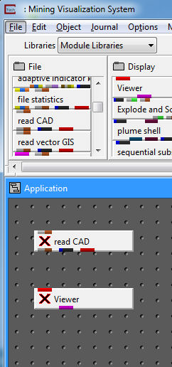
Next, go to the second column of modules shown above, called Display. Select the top module, labeled Viewer and drag it to the Application area directly below read_CAD. It may take a couple seconds for this process to be completed because the Viewer is the most comprehensive (and biggest) of all of the modules. When it completes, there should be another window in the upper left hand corner of your display, called C Tech Viewer.
At this point your window should look like the figure below.
In the Application area, place the mouse over the red output port on the bottom of read_CAD (as in the figure above), and press the left mouse button. At this point read_CAD should turn green as shown below.
If you move your mouse (while holding the left mouse button down) towards the Viewer, a white line will appear going from that port to the left (red) input port on the Viewer (with a red line going as well as to the bottom of the Application area).
Move the mouse until it is over the left-hand input port on the top of Viewer, and release the left mouse button. At this point your window should match the figure below.
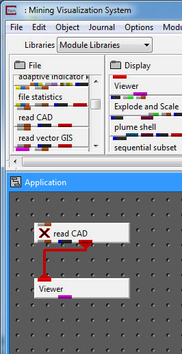
A thick red line will appear, connecting the output port of read_CAD to the input port of Viewer, as shown in the figure above. This graphical pipeline represents the data flow connection that EVS will use when you use read_CAD to load a file from in this application. To open the read_CAD module's user interface, merely double click on the read_CAD module and it will open (you can also use the mouse to click on the Modules pull-down list in the upper right hand portion of the Main EVS window). A browse dialogue box will appear.

Click on the Read DXF File button and a file browser will open.

Select the file CAB.dxf, and click on OK. The Viewer module renders the geometry and then displays it in a three dimensional viewer, as shown below. At this point our viewer is showing us a TOP view of this object.

EVS automatically normalizes and centers the object in the view. Once the object is centered in the view, it can be rotated by clicking and dragging on any part of the object with the left mouse button (see figure below). The object can be translated in the x-y plane by clicking and dragging it with the right mouse button. Try it now until you are comfortable with rotating, translating, normalizing and centering objects in the viewer.
Zooming of the object in the viewer is accomplished by depressing the shift and the left button (or a middle mouse button or wheel button without shifting) while clicking and dragging the mouse cursor towards the upper right corner of the viewer window (zoom in), or towards the lower left corner of the viewer (zoom-out). Try it now until you are comfortable with the zooming functions.

Workbook 1:covers these fundamentals in more detail and will introduce the process of 2D kriging of analytical (e.g. chemical) datasets.
© 1994-2018 ctech.com