![]()
General Module Function
The create_4DV module creates an animation script (*.4DV) for a 4DIM file.Once this script has been created itcan be used in one ofthree ways:
It can bebundled into the 4DIM using the bundle_4DV module (preferred method due to simplicity for end user)
The 4DV file script can be added to the 4DIM (as an available script)
Once the 4DIM (.4d) file is opened, if you double click (in Windows explorer) on the 4DV file is will automatically play.
Module Input Ports
1) lines_field (Blue-Black) : This port takes a field consisting of lines. This line field can come from the read_lines, draw_2D_lines, or draw_3D_lines.
Module Output Ports
1) path_field (Blue-Black) : This port outputs a field consisting of any Fly Through's the script will go through. This allows the user to see the exact path the Fly Through will take.
2) out_obj (Red) : This port outputs a renderable object consisting of any Fly Through's the script will go through.
Module Control Panel

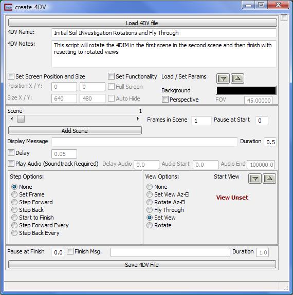
The global options for the create_4DV module can be seen in the image above.
The 4DV_Name is the name for the script you are creating. When selecting a script to run in 4DIM player or with the Playback_4DIM module, this name will be displayed.
The 4DV_Notes is used to describe the type of animation being created. When selecting a script to run these notes will also be displayed and can help distinguish one script from another.
The Set Screen Position and Size toggle will allow the user to set the size of the 4DIM and the position of the player.
The Set Functionality toggle will allow the user to set both the Full Screen toggle and the Auto Hide toggle. The Auto Hide toggle causes the play and file controls to be hidden when the mouse is not in the vicinity of the tool bars.
The Perspective toggle will turn on perspective viewing. This toggle will also cause the FOV(field of view) field to become active.
The Load / Set Params buttons will either load the position, size, and functionality settings from the 4DIM, or set the 4DIM settings from the create_4DV module.

The current scene options can be scene in the image above.
The Scene slider controls which scene is currently being edited.
The Add Scene button will add another scene to the script.
The Frames in Scene field sets the number of frames in the scene. A high number of frames will make any animations involving an interpolation (i.e. a rotation from one view to another) appear smoother, but will take more time. A small number of frames will make interpolated animations faster, but they will appear to jerk more between frames.
The Pause at Start field tells the 4DIM to pause before beginning the scene animation.
The Display Message text allows a message to be displayed in the 4DIM. This message will be displayed at the beginning of the scene and will last for the specified duration.
The Delay field gives the duration of the delay in seconds between each frame of the scene.
The Play Audio toggle will play the soundtrack bundled into the 4DIM from the specified start position to the specified end position. The Delay is in seconds from the start of the scene. The soundtrack is added to the 4DIM using the bundle_4DV moduel.
The Step Options are listed below:
1) None: No special stepping.
2) Set Frame: This will set the current frame in the 4DIM. This value is not related to the number of frames in the current scene.
3) Step Forward: This option will cause the frame in the 4DIM to advance once for every set number of frames in the Step Every field. So if the Step Every value is set to 5, for every time our current scene advances 5 frames the 4DIM frame will advance 1.
4) Step Back: This option is the same as above except that for every set number of frames in the Step Every field the 4DIM frame will go back 1 frame.
5) Start to Finish: This option will cause the 4DIM to advance from the Start Frame to the End Frame. The End Frame may be smaller than the Start Frame which will cause the 4DIM player to run in reverse.
6) Step Forward Every: Will cause the 4DIM player to step forward through every frame.
7) Step Back Every: Well cause the 4DIM player to step in reverse through every frame.
The two button groups Start Values and End Values will load the current frame from the 4DIM player into the appropriate box, or load the frame number from the current scene into the 4DIM.
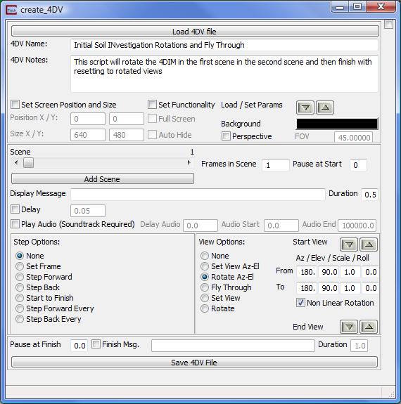
The View Options are listed below:
None: No view changes.
Set View Az-El: Allows the user to type in an Azimuth, Elevation, Scale and Roll. Views set in this manner are always OBJECT CENTRIC. To have more complex views or rotations, use options 5 or 6. These values can be loaded in from the 4DIM using the down arrow of the Start View button group. The 4DIM view can be set using the up arrow.
Rotate Az-El: Allows the user to rotate the view from a starting view to an end view. The start view can loaded in from the Viewer by setting Start and End positions in Az-El and using the down arrow of the Start View button group. Rotations set in this manner are always OBJECT CENTRIC. The end view can be loaded using the down arrow from the End View group. The current 4DIM view can be set using the up arrow of either group. A Non-Linear rotate will cause the view to rotate more quickly at the beginning and end, and more slowly in the middle.
Fly Through: This option will create a scene where the view follows a specified path. This path can be created by using either draw_2D_lines, draw_3D_lines or by creating and reading and EVS Line File (*.elf). Which line is followed can be specified using the Line # field. The Spline Path toggle will cause the fly through to be smoothed while still traveling through all of the points in the line. The Pitch, Scale, and Normalized Back Off can also be set for this fly through. The Pitch determines from which angle above or below the line you are looking at the next point. A Pitch greater than zero mean you are looking up from the current position along the line to the next position, equal to zero means you are looking directly down the line, and less than zero means you are looking down to the next position. The Scale term is used in the same way as the Az-El panel in the viewer. The Normalized Back Off value is discussed in the help for the fly_through module. The smoothness of the Fly Through is determined by the number of frames in the scene. For more information on these parameters, and for a more in depth discussion on fly throughs, please look at the help for the Control_Fly_Through module.
Set View: Allows the user to set arbitrary rotations, scale and translations using the mouse. The 4DIM view can be set using the up arrow.
Rotate: Allows the user to set arbitrary rotations, scale and translations using the mouse from a starting view to an end view. The start view can loaded in from the 4DIM using the down arrow of the Start View button group. The end view can be loaded using the down arrow from the End View group. The current 4DIM view can be set using the up arrow of either group. A Non-Linear rotate will cause the view to rotate more quickly at the beginning and end, and more slowly in the middle.
![]()
The script finish options are displayed in the image above.
The Pause at Finish field will cause the 4DIM player to pause for the specified time in seconds after the last frame of the last scene.
The Finish Msg. toggle will display the set message text for the Duration in Seconds.
The Save 4DV File will set the 4DV file name and create the 4DV file. This should be done after the entire script has been completed.
© 1994-2018 ctech.com