
This is a deprecated version of the slice module.
General Module Function
The Slice module produces a 2D subset of the data field along a slice plane arbitrarily positioned in the data field. The output of slice is a 2D surface that has the nodal data values within that surface. The remaining volume of the model on either side of the slice plane is not output from slice, only the values on the slice plane. The slice plane location and orientation is set in the Slice dialog box.
Module Input Ports
Slice has only one input port which accepts any 3D mesh. The mesh must be 3D and contain nodal data.
Module Output Ports
slice has three output ports.
The first port creates a 2D mesh containing the newly mapped values. The mesh is the mesh of the slice. It contains the slice's Node_Data
The second sends a renderable version of the slice to the viewer.
The third output port outputs to the cut module to provide the ability to control cut using the position of the slice plane..

Module Control Panel
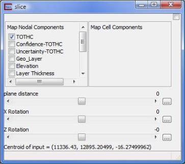
The control panel for Slice is shown in the figure above. A column of check boxes, titled Map Components, resides in the upper left corner of the dialog box. Below these, four slide bars are present. The topmost slider is titled plane distance, and the other three sliders are x rotation, y rotation and z rotation. These sliders are used to adjust the location and attitude of the slice plane.
Map component determines which model components will be sent to the leftmost output port in an unstructured mesh format. Also, the first map component selected will be the variable used to color the slice plane. For example, choosing the map component uncertainty will color the slice plane using uncertainty values interpolated from the nodes closest to the slice plane.
The plane distance slider moves the slice plane through the data field perpendicular to the current orientation of the slice plane. The default distance is 0.0. The minimum range is the (absolute value of maximum X-Y-Z extent - minimum X-Y-Z extent) * -0.5. The maximum range is the (absolute value of the maximum X-Y-Z extent - minimum X-Y-Z extent) * 0.5. The distance is measure from the spatial midpoint of the extents in all 3 axes. Because the extent may vary in different directions, the slice plane distance limits will usually exceed the extent in any direction. This can allow placing the slicing plane outside of the domain of the data. This will result in no slice being (generated) visible. If this occurs always start at zero (0.0) and determine the half extent in the direction of your displacement.
The x rotation, y rotation, and z rotation sliders control the attitude of the plane within the data field. Positive values (slider to the right) rotate the slice plane in a positive (clockwise) direction about each axis.
© 1994-2018 ctech.com