![]()
General Module Function
The incteractive_labels module allows the user to place formatted labels at probed locations within the Viewer. The data displayed is whatever data is visible at the
Module Input Ports
1) in_view (Purple) : This port takes input from the Viewer.
2) z_scale (Grey-Brown) : This port takes the z exaggeration factor.
3) f1 (Dark Brown) : This port takes a float value that can be used in the formatted label.
4) s1 (Greyish Blue) : This port takes a string value that can be used in the formatted label.
Module Output Ports
1) z_scale (Grey-Brown) : This port outputs the z exaggeration factor.
2) f1 (Dark Brown) : This port outputs the float value passed in via the input port.
3) s1 (Greyish Blue) : This port outputs the string value passed in via the input port.
4) out_obj (Red) : The port outputs a group renderable labels to the Viewer.
Module Control Panel

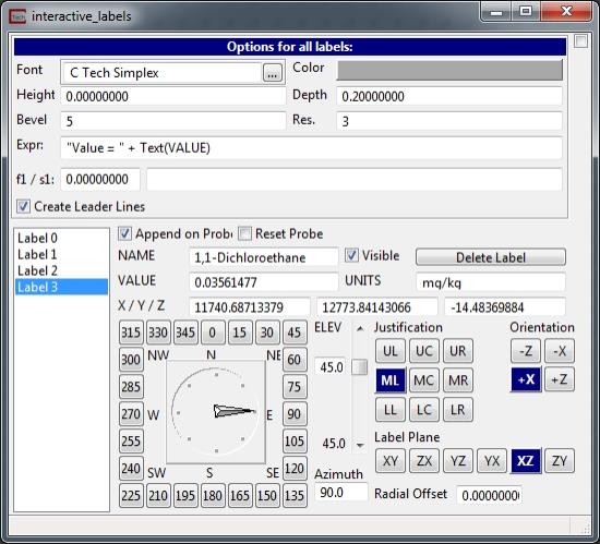
The Options for all labels window defines a group of parameters that are applied to all labels. These parameters cannot be set differently for individual labels.
The Font, Color, Height, Bevel, and Res. fields are the common font options for all labels.
The Exrpr: is the format string for the labels. The format string allows the same input as the string_format module with the additional variables of: NAME; VALUE; UNITS; X; Y; and Z. These additional variables correspond to the data values at the probed location.
The f1 field is a float field that can be passed in and allows for the f1 variable to be used in the expression.
The s1 field is a string field that can be passed in and allows for the s1 variable to be used in the expression.
There are many options that can be set for individual labels. The list box to the far left lists all of the labels created and the current label being edited.
The Create Leader Lines toggle will a leader line from the probed point to the label to be created.
The Append on Probe toggle will cause an additional label to be created when the Viewer has been probed in using the Alt + Left Mouse button.
The Reset Probe toggle when selected will allow the user to change the probe location of the label currently being edited.
The NAME, VALUE, UNITS, X, Y, and Z fields are populated based upon the displayed data at the probed location. Changing these values will not affect the data at the probed location.
The Visible toggle will turn on or off the currently selected label.
The Delete Label button will remove the currently selected label.
The Azimuth and Elev fields will rotate the label around the probed location.
The Radial Offset field allows the user to change the distance from the probed location to the label. There will be a line connecting the label to the probed location.
Justification, Orientation and the Label Plane are all label alignment options.
© 1994-2018 ctech.com