![]()
![]() ModulesPull-Down Menu
ModulesPull-Down Menu
General Module Function
The Viewer Module accepts renderable geometries from a broad variety of other EVS modules, renders the objects, and then outputs the display into a window that allows transformations and scaling of the objects using the mouse. The viewer tracks each object that gets sent to it individually or by groups of similar entities within an object, and organizes them into a parent\child hierarchy that allows direct assignment of properties to each object individually, or by inheritance from parent objects. There are also multi-window and single window viewers available. These viewers are not supplied by default with the EVS Viewer. This help section will describe the EVS viewer in detail. There are many options available to control the rendering and manipulation of objects in the viewer. An introduction to using the viewer is presented in some sections of Workbook 1 Mouse Transformation
Module Input Ports
The Viewer module is shown in the figure above, and has only one input port. This red port accepts input from all EVS modules that output renderable geometry.
Module Output Ports
The Viewer has one (magenta or purple) output port, which can be connected to many modules which process the full content of the Viewer. These include Output_Images, write_VRML, Record_4DIM, axes, etc. This port establishes a special type of connection between some modules like Output_Images and the Viewer which allows a virtual viewer to be established that can output an image at any user specified resolution.
There are a few keyboard shortcuts worth noting. These will give you quick control over the player.
CTRL-F sets the player to FULL SCREEN mode. This is not equivalent to the maximize button in the upper right corner since this removes the normal borders.
With the player as the active window, ESC(ape) exits Full Screen mode
CTRL-H toggles the Auto-Hide mode.
Object Manipulation in the Viewer
When the Viewer is instanced, it opens a window in which objects connected to the viewer are rendered and can be manipulated. Objects can be transformed and scaled in the Viewer window by using combinations of mouse actions and various keys on the keyboard.
Rotation of objects in the viewer is accomplished by either:
Clicking and dragging on any portion of the Viewer window with the left mouse button.
While the Viewer is the active window: After hitting the "R" key on the keyboard (not needed the first time, since this mode is default) the arrow keys ???? or the 4, 8, 6 & 2 keys on the NUM pad allow you to perform rotations about the Viewer's x & y axes similar to fundamental mouse rotations. The NUM pad keys 1, 7, 9 & 3 perform rotations about the diagonal axes.
Translation of an object in the x/y plane can be accomplished by:
Clicking and dragging on any portion of the Viewer window with the right mouse button.
While the Viewer is the active window: After hitting the "T" key on the keyboard the arrow keys ???? or the 4, 8, 6 & 2 keys on the NUM pad allow you to perform translations of your model in the Viewer's x & y axes similar to fundamental mouse translations. NUM pad keys 1, 7, 9 & 3 perform diagonal translations.
Zooming of an object in the viewer is accomplished by:
Depressing the Shift button while clicking and dragging the left-mouse towards the upper right corner of the viewer window (zoom in), or towards the lower left corner of the viewer (zoom-out).
While the Viewer is the active window: On mice with a wheel, depressing the wheel as a button and dragging towards the upper right corner of the viewer window (zoom in), or towards the lower left corner of the viewer (zoom-out).
While the Viewer is the active window: On mice with a wheel, rotation of the wheel in a forward direction zooms in and backwards zooms out.
While the Viewer is the active window: On the NUM pad, the "+" (plus) key zooms in and the "-" (minus) key zooms out. The "+/=" (plus-equals) and "_/-" (underscore-minus) keys on the main keyboard also zoom.
The user should work with the exercises in Workbook 1 to become comfortable with manipulating objects in the Viewer with mouse and key actions.
Distance Computations in the Viewer
The Euclidean distance between two points in the Viewer can easily be determined. First press the button in the lower right corner of the Viewer (shown below circled in RED).
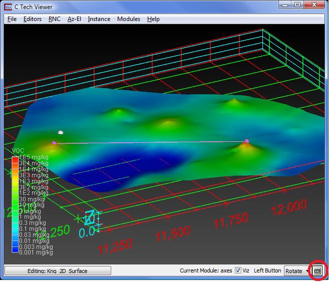
This will open a new panel that allows you to specify the Z Scale of the model in the viewer (this is not automatically set for you) and the radius of spheres that will be placed at each probed location. Distances are determined by using ALT+Left Mouse probing. The first point probed is the master point and each additional point probed after that will become the secondary point for distance computation.
To begin again with a new master point, use the "Clear Points" button.
When two points are probed, spheres will be place at each point and a purple (you can change this color) line will connect the points. The Distance panel displays the coordinates and data for each point and the Line Length (distance) between the points as well as the Slope and Aspect of the line.
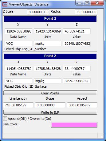
The line segment can be written to an ELF file and you may append or overwrite this file (append allows you to create a file with many line segments).
Viewer Module Control Menus

Above is an empty Viewer. The Modules pull-down menu is located on the Viewer and the main window of EVS.
Important Knowledge!: Many of the Viewer settings involve selecting a specific object in the viewer (Examples: making isolines thicker, coloring map lines, changing datamapping for plume_shell, etc.). This requires following the steps below for selecting objects in the Viewer.
Note that most of the operations listed below will effect only the selected object and those objects inheriting the settings. This feature is NOT under the editors pull-down, but instead is located in the bottom lefthand corner of the viewer. The button in the bottom left corner of the Viewer interface is named "Top" by default, which reflects the selected parant object (All Objects). Clicking this All Objects button (All Objects) activates the dialog box for selecting the object of interest from a list of objects in the view. The process for selecting objects in the Viewer generally requires:
Click the All Objects button.
Click on the desired object in the selector list of Viewer objects, then click Apply. The selected object's name should appear within the button, thus replacing the word "Top".
Adjust the attributes of the selected object (for example, change it's opacity setting).
Go back to the Object Selector list and click on Top, then click OK. Now, the word "Top" should appear on the face of the button again.
Note Selecting ojects can also be performed with the mouse by pressing the Alt key, then pointing to the object of interest in the Viewer window and clicking the left mouse. This selects the object, but to de-select the object you press the Alt key and click anywhere outside the rendered objects, in the "blank" area of your Viewer window (this area is usually black assuming a black background). Hint: You'll know you have properly selected or de-selected your object by seeing the word "Top" (on the button face) switch to your object's name, and vice-versa.
The Viewer has four control menus which are located along the top of the viewer window as shown in the figure above. The menus can be accessed by either clicking on them with a mouse, or by depressing the alt key and the underlined first letter of each menu title.
The first pull-down menu is "File" which includes the following items:

The first, second and last items are the same functionality as in the Network Editor (main window of EVS/MVS). These give you the ability to load and save applications, and exit the program. The "Restore and Close Network Editor" option provides a new ability to manage the windows on your desktop. With these, you can close the network editor and restore it.
This capability was also added to accommodate use with ArcView (copyright ESRI) extensions which launch EVS/MVS. The default mode will be to automatically load an application with data queried from ArcView and the network editor will normally be hidden. Users will be able to load and save their applications (parameter settings, etc.) without the Network Editor, but will be able to access it to customize their applications (add or delete modules).
Save Screen Capture as Image provides a means to save the image in the viewer window (not the border) at whatever resolution (size) your viewer is at the time. Though you can always create high resolution images with Output_Images, this provides a very quick and easy way to save images that are often adequate resolution. When this option is selected you will be prompted for a file name. Supported file types are Windows .BMP (the most common uncompressed file format) and PNG, the highest compression lossless file format. A confirmation window will pop-up when the file writing is complete.
Print Screen Capture provides a means to print the image in the viewer window (not the border) at whatever resolution (size) your viewer is at the time. Though you can always print high resolution images with the Print Editor, this provides a very quick and easy way to save print the contents of the viewer exactly as it appears at a resolution that is often adequate. When this option is chosen, a window (as shown below) will appear.
You have the following options:
Adding an Image Title and specifying the font type, size and color.
Including the date and time
Fitting the Image to the Page, in order to have the image scaled to fill out to the margins (and additional buffer for the title).
Specifying Margin Size in inches.
Stretch Preview Image. This option stretches the preview image to fit the preview window. It is most useful for the preview in the Print Editor where the output resolution may be so large that you cannot see the entire image. It may (probably will) cause distortion of the image aspect ratio during preview, but does not affect the output.
The Print button opens a dialog allowing you to specify the printer that you wish to use. You may set additional printer settings such as "Landscape" that will affect the final size and orientation.

Print High Quality provides the ability to create a high quality print of your image at any desired resolution.

The following provides hints and tips for obtaining the optimal quality from your printing device. This assumes you are using a color printer, but it is important to note that the user may print grayscale images with a black and white printer if desired. This would of course be best implemented by creating grayscale colormaps for the objects of interest (otherwise there will be ambiguous shades of gray that represent more than one color).
Printing: The following parameters and features are available:
Rendered Width and Rendered Height specify the resolution of the image to be printed and determine the image's aspect ratio (width divided by height). The width and height can be set to any (reasonable) value and may be set higher than the resolution of the current viewer window. Normally you will want to specify an aspect ratio that matches your current viewer.
Printer Pixels per Rendered Pixel is an integer type in the scales the image that is sent from the viewer to the printer. It doesn't change the resolution that the image is rendered to, but does scale up the image that the printer prints. This allows you to control the number of printer pixels (dots) that will represent each rendered image pixel. This is important if you want to have a specific printed image size and desire to achieve the highest level of print quality.
Note: If you use this, you should not use the Fit Image to Page option in the Print Preview window.
A detailed discussion of printing technology and specifications is available at the end of this topic.
The Background selector provides a choice of white, black or keep (to keep the current viewers background).
The Print button launches a sequence of processes that begins with rendering the current viewer objects at the specified resolution. When rendering is complete, the Print Preview window (as shown below) will appear.
In the Print Preview window the following options are available:
Adding an Image Title and specifying the font type, size and color.
Including the date and time as a label at the bottom of the page in the margin area
Fit Image to Page Fitting the Image to the Page, in order to have the image scaled to fill out to the margins (and additional buffer for the title).
Specifying Margin Size in inches.
Stretch Preview Image. This option stretches the preview image to fit the preview window. It is most useful for the preview in the Print Editor where the output resolution may be so large that you cannot see the entire image. It may (probably will) cause distortion of the image aspect ratio during preview, but does not affect the output.
The Print button opens a dialog allowing you to specify the printer that you wish to use. You may set additional printer settings such as "Landscape" that will affect the final size and orientation.
Color printers fall into three primary categories. They are: inkjet; color laser; and dye sublimation. EVS produces bitmaps which are continuous tone with 256 shades each of red, green and blue for a total of 16.7 million possible colors (256*256*256). Color printers must either produce continuous tones or approximate them using a pattern of primary colored pixels in an n-by-n grid.
Among these three printer categories there is considerable variation. Inkjet printers are (with a few exceptions) capable of producing one of only eight primary colors for each printer pixel (or dot). These colors are white, black, cyan, magenta, yellow, red, green and blue. Inkjets must therefore use a grid of primary colored pixels to approximate continuous tones. The larger the grid (4 by 4 vs. 2 by 2) the better the approximation. However, larger grids tend to create artifacts called jaggies, which are undesirable visually. The challenge is to balance the need for smoother color rendition with the desire to have higher resolutions.
Dye sublimation printers are at the other end of the spectrum. Their ability to reproduce continuous tones makes the task of choosing a resolution easy. A typical dye-sub printer has a resolution of 300 dots per inch (dpi). If the intended size of the final printed image is 10 inches wide by 7 inches tall, then the optimal image size is 10*300 by 7*300 or 3000 x 2100 pixels. If quicker image creation and print times are desired, a compromise resolution would be exactly half or 1500 wide by 1050 high.
IMPORTANT NOTE: We always want to have an integer number of printer pixels for each "rendered" image pixel. When we reduce the image size by half, we get a 2-by-2 grid. The n-by-n grid concept applies to ALL TYPES OF PRINTERS. This "rule" is actually a guideline for best results. Other resolutions (non-integer ratios) create banding artifacts that are usually objectionable.
For inkjet printers you should always allow for at least a 2x2 grid and usually 3x3 to 5x5 gives the best results. For an EPSON printer with 720x1440-dpi resolution you should use the smaller resolution number (720) for your calculations. The printer will use the additional resolution to better approximate the colors.
Example: For an Epson with 720 dpi, to print an image 9 by 7.5 inches (landscape) we recommend that you start at a 4x4 grid which gives an effective printed resolution of 180 dpi. Your image width and height would therefore be:
width = 9.0 * 180 = 9.0 * (720/4) = 1620
height = 7.5 * 180 = 9.5 * (720/4) = 1350
Finally, color laser printers vary in their abilities to approximate continuous tones. This means that the rules to apply will be somewhere between dye-sub and inkjet properties.
The first two options in this menu are:
Full Screen: Creates a Viewer which has minimal borders and is the full size of your graphics screen. You can turn this on/off with CTRL+F or using the Editors Pull-down menu.
Auto-Hide Controls: Further increases the effective area of the viewer by suppressing all borders and titles until the mouse approaches the top or bottom of the screen. This is great for presentations.
![]() BackgroundEditor Functions
BackgroundEditor Functions
![]() Camera EditorFunctions
Camera EditorFunctions
![]() Light EditorFunctions
Light EditorFunctions

One of the most common object properties that we change is the transparency (or opacity) of objects. This can be done within the Object editor menu as shown above.

Related to transparency is whether to cull (not display) surfaces whose normal vectors point away from you. For closed objects (like plumes) this generally makes display of transparency superior and less ambiguous. For unclosed objects (like a Krig_2D surface or topography) it can create situations where part of the surface when viewed from underneath.

Another important parameter is whether to compute object vertex normal vectors. When vertices (nodes) have computed normals, the surfaces are rendered with Phong shading making the surfaces much more smooth. However this also tends to round the edges of objects which can be objectionable. With Object.Normals Generation set to None, the faces of each cell are distinct and the edges are sharp.
The ObjectAdvanced Settings submenu provides several advanced options for altering the characteristics of parent or child objects. The user should not change most of the settings in the General menu unless they are very familiar with the rendering processes that control the Viewer module.

General Object Settings
The most important feature on the panel labeled General is the visible toggle which is also accessible on the bottom border of the Viewer itself. It provides a means to make any (selected) parent or child object invisible without having to disconnect that object from the Viewer.
On this panel you can also set whether an object is pickable (with Alt+Left Mouse), the Transform Mode (don't change this unless you understand the consequences), Cache Size, and VRML URL and Label.
RenderingModes

The Object Modes subpanel provides rendering options for points, lines, surfaces and model bounds. Settings for volume rendering are also supplied although seldom necessary due to easier interfaces in the volume_render module. Normally, objects are best left to Inherit the modes from the parent object, which has values that are most commonly desired. However, there are many occasions where modifying the modes of objects in the display is desired. Modes depend on the type of object. We will consider three primary types of objects Points, Lines and Surfaces. (The fifth mode, Bounds applies to all objects and consists of a box which surrounds the objects. This is used in EVS during rotation for certain objects.) Points do not have line or surface modes and lines do not have surface modes. Surfaces however, have all three possible modes.
The following options are listed along with the settings of most commonly used in EVS:
Point Rendering -- Inherit provides a default setting of NO point rendering. Pixel provides a single white point at each grid node of a surface or grid. Directed puts normal vector (porcupine quills) at each node. Tangent cross puts a "+" tangent to the surface at each node (only in OpenGL). Smooth Dot draws an anti-aliased fuzzy dot at each node (only in OpenGL).
Line Rendering -- Inherit provides a default setting of NO line rendering. Regular and Ribbon provide similar rendering of lines around each polygon of the selected surface(s).
Surface Rendering -- Inherit provides a default setting of Gouraud Shading resulting in a smooth (gradational) linear interpolation across any selected color range. No Light colors the objects a solid bright color (no lighting effects). Flat applies lighting effects, but colors triangular regions a solid color (no gradient shading), thus giving a faceted appearance to surfaces. Background makes all surfaces the color of the background. This may seem like no shading until you combine this with regular line mode.
Volume Rendering -- This rendering type is only supported with uniform fields with two byte integer input. Choosing software renderer allows rendering via a ray tracing technique, while choosing OpenGL allows Back To Front (BTF) rendering. These settings are best adjusted from within the volume_render module.
Bounds Rendering -- Inherit provides a default setting of NO bounds rendering. Selecting Bounds results in a wire rectangular box around the current x, y, z extents of the selected object.
Normals Generation -- Inherit provides a default setting of Vertex normals which allows for surface interpolation between neighboring polygons. Selecting None results in flat surface polygons and thus creates a faceted appearance on surfaces. Sometimes a "None" setting is desirable when rendering cut or external faces.
Object Properties
The Object Properties submenu allows the user to change the colors, material characteristics, and line characteristics used to display objects in the Viewer. There are three radio button selectable items in Object Properties, and each brings up a window with controls for changing these characteristics.

The Surface Type submenu presents sliders for surface lighting properties, surface reflection (shininess) and opacity.
The ambient and diffuse sliders affect the brightness of objects with respect to ambient (non-directional or lambertian reflection) and diffuse (directional or specular reflection).
The Specular and Gloss sliders determine the brightness and focus of white specular highlights on objects whose surface normal reflects the directional light source back to the viewer. This could also be considered shininess.
Of particular importance in this window is the Transparency slider, which can be used to set the transparency of objects in the viewer. A transparency value of 1 sets the object to be opaque, and a value of 0 makes the object completely invisible.
Culling Mode may be a useful adjustment if visibility problems arise using transparency. Try front culling on the object of interest if the rendering is not satisfactory with your opacity setting.

The Point/Line Type submenu presents line style choices and sliders for line and point display.
Line Style can be solid, dashed, dotted, and dashed-dotted.
A choice of Copy and Xor Drawing Mode is presented, but EVS users should always use Copy (default).
The Line Thickness slider default is '0'. The Line Thickness slider sets the width of lines in pixels, and can be set to values ranging from 0 to 25. Zero is a special fast version of one pixel wide. The user will need to experiment with line widths to achieve the desired display.
Glyph Size applies only to special geometries.
The Subdivision slider controls the number of element subdivisions to be performed before drawing of lines along surfaces (grids). The higher the number, the more accurately the lines will be placed through the data. Higher accuracy does not always cause the lines to become smoother, depending on the data distribution. The default subdivision levels is four, and the maximum is 20.
The Smooth Lines toggle creates a (sometimes) -pleasing display of lines. The jagged display along pixel divisions is darkened and blurred to create a somewhat smoother (softer) appearance. Smooth lines produces thicker anti-aliased lines.

The General Type submenu presents a set of RGB value dials that will change the color of the selected object. The primary color can only be changed on objects which do not have colors already assigned to them. The extract_mesh module provides a means to strip off nodal data (and hence surface colorization) from objects.
The Primary Color submenus are used to change the color of highlight reflections on rendered objects with specular (or metallic) surface characteristics. These are not widely used in scientific visualization.
The Secondary Color submenus can used to change the color of lines in DXF files.
Background Editor
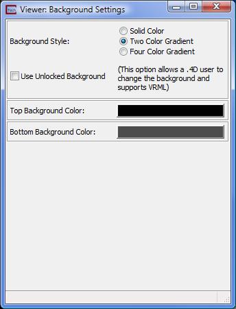
The background editor options are shown below.

The advanced settings allow you to specify either a two color or four color gradient background. These "Locked" backgrounds cannot be changed in a 4DIM file. The two color style is shown below:
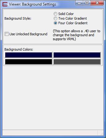
And the Four Color Gradient options are:
The background settings above result in the following Viewer appearance:


The menu above provides a quick way to switch between OpenGL and Software Renderer.
The View Advanced Settings provides the user with additional feature rich submenus for changing viewer properties such as renderer selection, depth sorting, viewer window size, and even support for Stereo displays. Each of the submenus invokes a dialogue window with type-in options and/or toggles.

The General submenu contains most of the EVS user functionality and is shown in the figure above.
The Renderer pulldown list provides the option for either OpenGL or Software rendering.
The OpenGL renderer is a high performance renderer which is native to the Windows operating system, and is the default option. For most objects, OpenGL rendering provides much faster rendering performance than the software renderer, and is the default setting.
However, the Software renderer provides some functionality that the OpenGL renderer does not, and therefore is the desired option for some operations. Specifically, spheres are calculated in the software renderer much more quickly and efficiently then OpenGL which renders a many faceted object. If you are visualizing a large number of spheres you should choose the software rendering option. The other important difference is that the Software Renderer support Depth Sorting when your view has multiple transparent objects.
When there are two or more transparent objects in your view, without depth sorting the appearance of which object is in front or behind can be improperly displayed. Properly displaying multiple transparent objects requires sorting the object's order of display based on their apparent position relative to the observer. There are two different depth sorting options, each requires progressively more computation and is therefore increasingly slower than normal rendering.
Remember that these options are not available in OpenGL since none of the graphics card manufacturers support this level of sophistication.
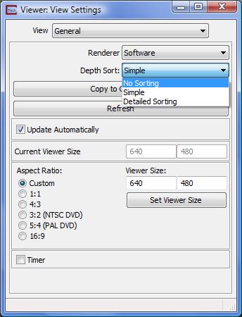
The Viewer Size type-ins control the Width and Height of the viewer window. The default is sized automatically by EVS depending on your computers display resolution. You may size the viewer window with your mouse or by using these type-in boxes.
The Aspect Ratioselectors let you control the aspect ration based on the current width. This is a quick way to set a viewer shape that matches many standard output formats.
The Timer checkbox activates an internal clock which allows benchmarking of system hardware performance in terms of rendered screens per second. To use the timer, select this toggle and "throw" the object in the viewer. A throw is a method of rotating the objects in the view in a continuous fashion. To throw the view, start a rotation (left mouse button click...hold...and move) and release the button while the cursor is in motion. The next time you click (left mouse button) in the viewer it will stop the throw and performance stats will be printed to the right of the Timer toggle.

The Stereo submenu allows for Stereo viewing of objects and gives slider choices for Balance and Separation Offset. This functionality must be used in conjunction with special hardware. Please also note that in order to activate Stereo viewing, you must turn on Stereo Enabled, save your application and shut down EVS. Upon restarting and loading your application, the Stereo On toggle turns this on and off. Since Stereo Enabled uses so many resources, this roundabout method is required.

One of the most common camera features to change is Autonormalize. This function causes the view to automatically scale and center about all of the objects in your view. Though incredibly useful when you are building your application and loading data, this feature can be very annoying when you are making small changes to your application.
Another quick feature is whether to use Perspective. Remember this function is also on the Az-El panel.
The CameraAdvanced Settings menu provides the user with 5 submenus for changing camera properties such as the camera positioning, perspective and auto-normalization options. Each of the submenus invokes a dialogue window with type-in options and/or toggles.

The General submenu contains the Auto Normalize option which is Data and Object by default which results in renormalization of the viewer whenever a new module is connected to the viewer or whenever an object's mesh is changed in any way. Any combination of the above is possible such as Auto Normalize on data (mesh) change only or object attach only, or none (Auto Normalize Off). All other settings in the General submenu should be left to the defaults by EVS users.
The lower half of this panel provides the main controls for perspective viewing. Perspective is an important feature, which is off by default. Normally we use a non-perspective view, which displays parallel lines as parallel. Objects are the same size regardless of their distance from the viewer. Perspective gives a view that can be likened to a camera view through a wide-angle lens. It sometimes seems more realistic, but perhaps less scientific (quantitative). The perspective option is used in conjunction with the Field of View slider at the bottom of the panel. Generally, objects will appear the same size (but distorted) with a 45 degree perspective view and the default view. A smaller Field of View is like zooming in on the display and reduces perspective effects. You can compensate for changing Field of View by adjusting the Viewport Size, changing the Scale Factor (on the Az-El panel), zooming in/out, or translating the objects in the "z" direction (shift right mouse button).

The Tripod submenu provides means of positioning the camera from a specified 'ground' to a tripod height and also through changing the actual 'ground' position and orientation of the tripod. This is difficult to set manually, but it is this functionality that is automatically driven by our fly-through and fly-over applications.

The Clipping Planes submenu provides tools for actually clipping away visibility of objects either near or far from the camera. Clipping can be turned on and off and the front or back planes can be moved with sliders to control clipping and z-buffering for the depth of view that is displayed in the window.

The Depth Cueing submenu provides an on/off toggle and three sliders for controlling front, back and scale. Depth Cueing is an advanced display option, which controls the fading of the light based on the distance objects are from the viewer.
The user should experiment with different settings of the options in the Camera Editor Control Panel to understand the functionality of each. However, each time that a Viewer module is instanced, it is reset to have the default values, so no permanent changes to the camera are saved between sessions. However, camera settings are saved with Applications.

The two most commonly modified light features is whether to show the lights and to manipulate (transform) the light versus the objects in the Viewer. These two features can be controlled from the pull-down menu.
The LightAdvanced Settings menu provides the user with submenus for changing the characteristics of the ambient and directional lights that are being used to render the objects in the Viewer.

The General submenu allows for adjustment of four different directional lights (numbered 0 through 3). Each can be controlled using the Type selector (BiDirectional, Directional, Spot or Point).

The Light On toggle controls which of the directional lights is being operated on with the color (dials or sliders) and Attributes submenu. Each light can be set to have different characteristics to achieve the type of lighting the user wishes for the display in the Viewer.

The Ambient submenu allows color adjustment of an ambient light source. The ambient light can be turned on or off by checking the Light On toggle, and its color can be modified using an RGB slider or dial control.

The picture above demonstrates adding a Spot light to highlight an area of a 3D model.


The Light_Editor has been enhanced to include a button which switches between "Transforming Object" and "Transforming Light". When "Transforming Light" is selected, your mouse (or the Transform Editor) will rotate the light. This is useful for enhancing surface topography and features. In many cases, you may want to switch to "Directional" vs. "Bi-directional" lighting.
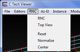
The RNC menu presents the user with buttons that will reset, normalize and center objects in the viewer. The Reset button resets the Viewer coordinate system to that of the objects so that the viewer space is consistent with a right handed system that has the +Z axis pointing toward the user. The Normalize button zooms the object so that it fills the width of the Viewer area. The Center button sets the center of rotation for the object to the center of the screen, so that rotating objects will remain on the screen. If the object is not centered in the viewer window, then rotations will occur around the origin at (0,0,0), which may move the object out of the viewer. Pressing the RNC buttons sequentially will always reset the center of rotation to have the geometric center of the object coincide with the center point of the viewer.

The Az-El panel provides the ability to set specific views using a variety of controls. These include:
A combined Azimuth dial or button array The panel is arranged with an array of azimuth selection buttons in 15 degree increments around the compass, and a dial for setting any azimuthal location. There is also a type-in box for setting a precise azimuth. An interesting feature is that if you move the dial with your mouse, as you cross North, it will add or subtract 360 degrees from the button values. This is important during animations since rotations crossing north must be properly specified to determine the direction and number of revolutions of your model.
An Elevation slider (and type-in) sets the angle of the view from horizontal plane. An elevation value of +90 will result in a view from directly above the object (looking straight down the +Z axis), while an elevation value of -90 will result in a view from directly below the object (looking straight up the -Z axis). For example, a value of +20, provides a view looking at the object from 20 degrees above the horizontal plane. Note that changing any of the settings on the Az-El panel updates the current view immediately.
A Scale Factor slider (and accompanying type-in) allows the user to specify how much of the Viewer width the object(s) will occupy in the specified perspective view. A Scale Factor of 0.7 will therefore produce a display with the object occupying approximately 70% of the Viewer. Values above 1.0 will generally cause some of the model to be outside of the viewer window.
The RNC (Reset-Normalize-Center) button with the tri-color icon in the upper left corner of the panel forces a recentering of the model and sets the view to the current Az-El settings. Furthermore, this button causes the Viewer to RENORMALIZE, which means that it recomputes the internal system wide scale factor required to fit all objects connected to the Viewer into the current view. Please note that the RNC pull-down menu on the Viewer includes a "Top View" option that is equivalent to this button PLUS resetting all Az-El parameters to their default settings.
An important feature for creating simple animations and automating viewer manipulations is the Spin toggles and it's associated 'steps' type-in box. The type-in specifies the number of degrees to spin the viewer azimuth and the '>' and '<' toggles determine the direction of spin. Use of this functionally essentially activates a loop whereby checking the '>' or '<' toggle increments the viewer azimuth according to the prescribed 'steps' type-in. For example, if you wish to automate views incrementing every 10 degrees with a clockwise rotation, you should type-in 10.0 (steps) and check the '>' toggle. The viewer will automatically step through from the beginning azimuth in 10.0 degree increments, in a clockwise direction. This spin can be stopped (interrupted) at any time by unchecking the '>' toggle. HINT: You may connect an output_images module to the viewer, then check the dynamic toggle to save a frame of each viewer position for use in building an animation.
The Perspective toggle turns on Perspective mode. When it is turned on, an additional type-in for FOV appears. Additional settings for perspective are under the Camera editor.
FOV (Field of View) sets the camera's included angle when in Perspective mode. The default value of 45 results in a camera with a 45 degree included field of view.

The Seek button works in conjunction with the zoom type-in. After first renormalizing (hitting RNC), if you use the Alt+Left mouse button to select a location on any pickable object. At this point you should see the dark gray corner of the Az_El panel display the Seek button. Pressing this will cause the view to center on your selected point and zoom in by the zoom factor (default is 2). Subsequent pressing of Seek will continue to zoom in on the selected point.
The Immediate toggle turns on immediate mode for scale and elevation sliders and the Azimuth dial. In immediate mode the view updates in real time as you move these controls.

The Text button opens a Text Output Formatting window which allows you to create a text string for titling that contains view transformation (Azimuth, Scale, Elevation, and/or Roll).
The formatting options are identical to those used by the string_format module. Some examples are:
"Azimuth: " + Text(f1,0) + ", Elevation: " + Text(f2,0) + ", Scale: " + Text(f3,1) + ", Roll: " + Text(f4,0)
Displays all parameters with zero decimal points for Azimuth, Elevation and Roll and one decimal point for scale.
"Azimuth: " + Text(f1,1) + ", Elevation: " + Text(f2,1) + ", Scale: " + Text(f3,2)
Displays Az, El, and Scale only with one decimal points for Azimuth, Elevation and two decimal points for scale.
Advanced Transformation Options
Options for advanced transformations are available by clicking the small 'adv' button located beneath the + button on the Az-El panel. Selecting this button provides XYZ dialogue boxes for changing the center of rotation for the object(s) in the viewer, and for translating the object's position within the viewer screen.

The values for the XYZCenter and Translate type-ins are automatically set when you renormalize or Seek. Normally the user will not change these values manually.
The Roll type-in and dial allows you to control the Roll of objects. This is a rotation that is not normally used since it causes vertical objects to not be vertical. It can be interesting for some fly-through animations or for unusual circumstances.
The type-in along the bottom of the window provides probing information about a point selected with the Alt+Left mouse button on any object. This includes coordinates, the nodal data (first data component) and the node number.
Nearly all of the Sample Applications include the Viewer module, and the user can work through the tutorial in WorkBook 1 to gain an understanding of its operation.
© 1994-2018 ctech.com