![]()
(This module is available only in MVS)
General Module Function
The strike_and_dip module is used to visualize sampled locations. It places a disk, oriented by strike and dip, at each sample location. Each disk is probable and can be colored by a picked color, by Id, or by data value. If an ID is present, such as a boring ID, then there is an option to place tubes between connected disks, or those disks with similar Id’s.
Strike and dip refer to the orientation of a geologic feature. The strike is a line representing the intersection of that feature with the horizontal plane (though this is often the ground surface). Strike is represented with a line segment parallel to the strike line. Strike can be given as a compass direction (a single three digit number representing the azimuth) or basic compass heading (e.g. N, E, NW).
The dip gives the angle of descent of a feature relative to a horizontal plane, and is given by the number (0°-90°) as well as a letter (N,S,E,W, NE, SW, etc.) corresponding to the rough direction in which feature bed is dipping.
We do not support the Right-Hand Rule, therefore all dip directions must have the direction letter(s).
Module Input Ports
strike_and_dip has a one input port (gray-brown) to provide the Z Scale factor
Module Output Ports
strike_and_dip has three output ports:
The leftmost (gray-brown) port is the Z Scale factor.
The second (blue-black) port outputs a field comprised of three cell data components : strike, dip, and Data
The third (red) port outputs a geometry, along with tubes, that can be connected to the Viewer for rendering.

Module Control Panel
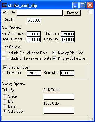
The control panel of strike_and_dip is shown in the figure above. The Browse button opens a File Browser which lists the *.sad files that are present in the current directory shown in the directory window. The format of .sad files is described in the SAD file format help topic.
Note that this module will not begin running until a valid SAD file has been selected.
Disk Options:
Min Disk Radius: This sets the minimum radius for each disk. The coordinates are in
model coordinates.
Thickness : This value sets the thickness of each disk. The coordinates are in
model coordinates.
Radius Extent: The disk radius is based upon a percentage of the x, y, and z extents
of the model.
Resolution: Number of prisms used to make each disk. The greater the number of
of prisms the more "round" the disk. Resolutions based on a factor of
of four are recommended as they will allow the dip and strike lines to
end at the extents of the disk.
Line Options:
Include Dip values as Data: This allows you to color the Dip lines based upon the dip angle.
Include Strike values as Data: This allows you to color the Strike lines based upon the strike
angle.
Display Dip Lines: This toggle turns the Dip lines on and off.
Display Strike Lines: This toggle turns the Strike lines on and off.
Tube Options:
Display Tubes: This toggle turns the tubes on and off.
Tube Radius: This is the radius for the tubes, set by default to be 2 percent of the extents of the model
Resolution: This alters the number of sides each tube has, the more sides the more "round" the tubes will look, and possibly the slower they will display.
Display Options:
Color by Strike: Colors the disks and tubes by the Strike angle.
Color by Dip - Colors the disks and tubes by the Dip angle.
Color by Data - Colors the disks and tubes by the Data value.
Color by Solid Color: Allows the user to select a constant colors for both disks and tubes.
Discussion of Strike and Dip Files
Strike and dip files consist of 3D coordinates along with two orientation values called strike and dip. A simple disk is placed at the coordinate location and then the disk is rotated about Z to match the strike and then rotated about Y to match the dip. An optional id and data value can be used to color the disk.
Format:
You may insert comment lines in C Tech Strike and Dip (.sad) input files. Comments can be inserted anywhere in a file and must begin with a '#’ character.
Strike can be defined in the following ways :
1) For strikes running along an axis:
N, S, NS, SN are all equivalent to 90 or 270
E, W, EW, WE are all equivalent to 0, 180 or 360
NE, SW are both equivalent to 45 or 225
NW, SE are both equivalent to 135 or 315
2) For all other strikes: any azimuth direction between 0 and 360 degrees
Dip can be defined only as a degree followed by a direction such as 35E.
There is no required header for this file type.
Each line of the file must contain:
X, Y, Z, Strike, Dip, ID (optional), and Data (optional).
NOTE: The ID can only contain spaces if enclosed in quotation marks (ex "ID 1").
EXAMPLE FILE
# x y z strike dip
51.967 10.948 26.127 -5.205 59.803188E
50.373 33.938 26.127 13.048 68.499864E
51.654 60.213 26.127 -9.108 76.742125E
50.529 83.203 26.127 -13.50 62.945989E
64.358 76.634 11.471 -14.23 80.386294E
66.430 33.938 -6.849 -1.421 60.385837E
75.901 50.360 -21.505 -0.141 72.88960E
72.943 7.663 -21.505 5.255 65.512417E
101.90 30.654 -72.801 -7.675 65.952504E
81.339 50.360 -43.489 -4.285 70.707799E
72.263 73.350 -21.505 -2.929 69.314259E
89.897 73.350 -61.809 -4.531 55.678350E
END
FILE TAGS:
The file tags for the ASCII file formats (shown in Bold Italics) are discussed below with a representative example. They are given in the appropriate order. If you need assistance creating software to write these file formats, please contact support@ctech.com.
COORD_UNITS "ft"
Defines the coordinate units for the file. These should be consistent in X, Y, and Z.
END (this is optional, but should be used if any lines will follow your actual data lines)
© 1994-2018 ctech.com