![]()
General Module Function
Output_Images will produce virtually all types of bitmap images supported by Windows. The most common types are .png;.bmp;.tga;.jpg; and .tif. PNG is the recommended format because it has high quality lossless compression.
Output_Images also allows automatic creation of images for using with modules such as advector or with fly-over loops.
Module Input Ports
Output_Images has only two input ports. The leftmost port only connects to the EVS Viewer and the right port connects to Read_Image and other modules that output images (e.g. image_transition).

Module Control Panel
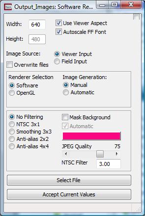
The control panel for output_images is shown in the figure above. The user can specify the size of the virtual viewer using the Width and Height edit fields.
The Width and Height edit field are used to specify the number of pixels in the horizontal and vertical direction used to define the virtual viewer. These edit fields default to a width of 640 and a height of 480 (640x480) and their maximum is 4000. A Larger number of pixels creates better resolution, much larger files and longer creation times. See Printing Quality Tips at the end of this help topic for information on resolution, as it relates to printing devices and color reproduction.
If the Use Viewer Aspect toggle is selected, the height of the image will be automatically be determined based upone the aspect ratio of the Viewer and the selected image Width.
When the Autoscale FF Font toggle is selected all Forward Facing fonts in the image will be scaled depending upon the size of the output image.
The suffix specified for the output image file determines the type of output.
For PNG (portable network graphics), a compression slider is provided. The max value of 9 results in a very small increase in compute time for compressing the images. Since PNG is a LOSSLESS compression format, the quality of the image is not affected by this value.
For JPEG, a quality slider is provided. Higher qualities result in less LOSS to the image but create much larger files. We recommend using PNG instead of JPEG whenever possible. The PNG images are often smaller and are always higher quality than a JPEG image.
The Image Generation Manual and Automatic toggles determine whether the image will be created upon hitting Accept Current Values, or automatically create an image after each viewer change. For instance, the Automatic feature works well if you would like to save every advector step in an advector application run.
The Renderer Selection Software or OpenGL toggle determines the renderer to be used during image creation. The default is for Software rendering and will ignore the rendering currently chosen in the Viewer. Choosing OpenGL will utilize the OpenGL renderer in your graphics card. Depending on the capabilities of your card, you can write images up to 4096 x 4096 pixels (some professional cards may be able to go to 8192 x 8192).
Filtering: To enhance the quality of images (especially for video output to NTSC DVD) a number of filtering options have been added. The default is No Filtering and is most appropriate for output that will be printed to color printers. The other options should generally be used when creating .avi files or output to NTSC video where the resolution is limited by the media format.
The NTSC (3x1) option is the quickest filter for NTSC (standard television) animation. NTSC video standard uses pairs of interlaced fields which contain odd and even pixel scan lines (respectively). Horizontal single pixel wide lines will flicker when viewed in NTSC. To minimize this effect, a blurring filter is used to blend lines to more than one horizontal pixel row. The value of this filter determines the level of blurring. A value of three is a reasonable starting point. A non-zero value, N results in a blurring which places N/(N+2) of the pixel's original color at the center and 1/(N+2) above and below the scan line. Small values of N therefore produce more blurring.
Smoothing 3x3 is similar to NTSC, but blurs the image in the row direction and the column direction.
The Anti-alias options are very different, and slow the image creation process. These options actually render an image that is twice as big as the specified Width and Height. This high resolution image is the filtered and subsetted to the specified size. This process reduces the brightness (contrast) of fine lines but it also smooths the lines and dramatically reduces jaggies. The 4x4 option with an NTSC Filter value of ~8.0 produces great results.
The Mask Background toggle allows you to create an image with a transparent background. In order to accomplish this, several things must be done:
You must specify an image type that supports transparent backgrounds. PNG is recommended
You must have a background color which is unique from any pixels in your objects which are rendered. This can be somewhat difficult if you have a rendered object with shading and specular highlights. Shading creates darker versions of the colors in your datamap and specular highlights creates less saturated (more white) versions of those colors. To avoid creating object colors that match your background, a masking background color should be selected which has a unique HUE not found in your datamap.
When the Mask Background toggle is on, the Automatic toggle becomes active (selectable).
With Automatic ON, upon rendering the image, the background color is temporarily changed to the color shown in the color button (default is a pink magenta), the image is rendered and your background is returned to normal.
With Automatic OFF it still uses the color on the color button as the mask but expects you to set your background.
Anti-Aliasing and filtering will intelligently detect the edges that are transparent and not mix in "pink" edges on your objects.
NOTE: There is no tolerance for matching the background color. The color must match the RGB value exactly.
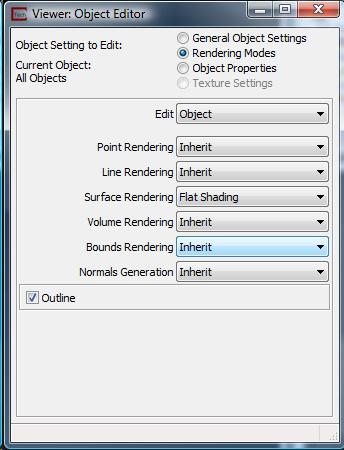
TIP: The mask background function can be used to create transparent HOLES in your images. For example, a lake, which is rendered as a unique color could become a transparent hole in your rendered output. In order to accomplish this, the object which represents the lake must be colored to exactly match your mask color and it must have its surface rendering set to "Flat Shading".

The Select File button is used to bring up a standard windows file browser for choosing the name and location of the file to create. The Accept Current Values push button begins creation of the file.
When a file name has been selected using the Select File push button and all other parameters are set, the Accept Current values push button is used to create the file. When this button is selected, the EVS Status Window should indicate that the type of file being created. Nothing will happen when this button is pushed if 1.) No file has been selected, or 2.) no data is being sent to the input port of Output_Images.
The following provides hints and tips for obtaining the optimal quality from your printing device. This assumes you are using a color printer, but it is important to note that the user may print grayscale images with a black and white printer if desired. This would of course be best implemented by creating grayscale datamaps for the objects of interest.
The print features in EVS & MVS allow you to specify the resolution of the rendered bitmap image that will be used for output to a printer. The process for determining the optimal size (width and height) requires taking several factors into consideration.
First, you must know the characteristics of the printer and the size of the printed image. Printers vary considerably and no single recommendation can be appropriate. Color printers fall into three primary categories. They are: inkjet; color laser; and dye sublimation. EVS produces bitmaps which are continuous tone with 256 shades each of red, green and blue for a total of 16.7 million possible colors (256*256*256). Color printers must either produce continuous tones or approximate them using a pattern of primary colored pixels in an n-by-n grid.
Among these three printer categories there is considerable variation. Inkjet printers are (with very few exceptions) capable of producing one of only eight primary colors for each printer pixel (or dot). These colors are: white, black, cyan, magenta, yellow, red, green and blue. Inkjets
must therefore use a grid of primary colored pixels to approximate continuous tones. The larger the grid (4 by 4 vs. 2 by 2) the better the approximation. However, larger grids tend to create artifacts called jaggies which are undesirable visually. The challenge is to balance the need for smoother color rendition with the desire to have higher resolutions.
Dye sublimation printers are at the other end of the spectrum. Their ability to reproduce continuous tones makes the task of choosing a resolution easy. A typical dye-sub printer has a resolution of 300 dots per inch (dpi). If the intended size of the final printed image is 10 inches wide by 7 inches tall, then the optimal image size is 10*300 by 7*300 or 3000 x 2100 pixels. If quicker image creation and print times are desired, a compromise resolution would be exactly half or 1500 wide by 1050 high.
IMPORTANT NOTE: We always want to have an integer number of printer pixels for each "source" image pixel. When we reduce the image size by half, we get a 2-by-2 grid. The n-by-n grid concept applies to ALL TYPES OF PRINTERS. This "rule" is actually a guideline for best results. Other resolutions (non-integer ratios) create banding artifacts that are usually objectionable.
For inkjet printers you should always allow for at least a 2x2 grid and usually 3x3 to 5x5 gives the best results. For an EPSON printer with 720x1440 dpi resolution you should use the smaller resolution number (720) for your calculations. The printer will use the additional resolution to better approximate the colors.
Example: For an Epson with 720 dpi, to print an image 9 by 7.5 inches (landscape) we recommend that you start at a 4x4 grid which gives an effective printed resolution of 180 dpi. Your image width and height would therefore be:
width = 9.0 * 180 = 9.0 * (720/4) = 1620
height = 7.5 * 180 = 9.5 * (720/4) = 1350
Finally, color laser printers vary in their abilities to approximate continuous tones. This means that the rules to apply will be somewhere between dye-sub and inkjet properties.
© 1994-2018 ctech.com