![]()
General Module Function:
The overlay_aerial module will take as input a field and then map an image onto the horizontal areas of the grid. The image can be projected from one coordinate system to another. It can also be georeferenced if it has an accompanying All vertical surfaces (Walls) can be included in the output but will not have image data mapped to them.
Module Input Ports:
1) surface_to_texture (Blue-Black): This port accepts the grid to be mapped onto.
2) filename (Grey-Blue-Grey): This port allows for sharing the image filename.
Module Output Ports:
1) filename (Grey-Blue-Grey): This port allows for sharing the image filename.
2) out_surfaces (Red): This port outputs the mapped renderable object.
3) out_walls (Blue-Black): This port outputs the vertical surfaces. This can be used to texture map the vertical surfaces.
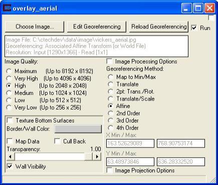
Module Control Panel:
Choose Image: This button will bring up a file browsing menu to allow for the selection of the image file from among the following types:
*.png
*.bmp
*.jpg
*.jpeg
*.gif
*.hav
*.avi
*.mpg
*.bay
*.giff
*.pcx
*.pnm
*.ras
*.sun
*.rgb
*.sgi
*.tif or *.tiff
*.xpm
*.sid"
Edit Georeferencing: This button will bring up a window that will allow either a world file or GCP file to be created. NOTE: Please examine the Utility help section titled Georeference Image for instructions on how to use this feature.
Reload Georeferencing: This button will cause the file to be re-read and any new georeferencing created with the Edit Georeferencing button.
Image Processing Options: This toggle will bring up a window that allows for the adjustment of image brightness, sharpness, etc..
Image Quality: This selector limits the max resolution of the image being read. Most graphics cards support the High resolution of 2048, but relatively few support 4096 and only professional level cards and some of the newest DirectX 10 cards support 8192. Obviously higher resolution images will take more memory and more time to read, but will look much better when zoomed in.
Georeferencing Method: There are 8 different texture mapping modes as follows:
1) Map to Min/Max - Map image to the min/max extents of the input surface, or a user-defined value (can be typed into overlay_aerial directly).
2) Translate - Translate the image. Only requires a single GCP. No rotation or scaling is performed.
3) 2 pt: Trans./Rot. - Translate, Scale, and rotate the image. The image scaling is always the same in X&Y. Only a valid option if you have 2 GCPs. Good option if you only know 2 GCP points, and they are co-linear or near co-linear.
4) Translate/Scale - Translate and scale the image. Scale in X and Y are not the same. This keeps the image orthorectified. Can be used with 2 or more GCP points.
5) Affine - Perform a full affine transformation (1st order transformation) on the image. Requires a world file or 3 or more GCP points (from a gcp file). This is the default option which can be fully described with a World File.
6) 2nd Order - Perform a 2nd order polynomial transformation. This requires 6 or more GCP points (from a gcp file). It will map straight lines in the image into arcs. Allows an image that was georeferenced previously into LAT/LON coordinates to be "straightened" out and handled correctly. This can also be used to adjust for minor problems in the image due to topography. This option cannot be described with a World File because it uses a second order polynomial with more terms than are available in a world file. It requires the use of a GCP file.
7) 3rd Order - Perform a 3rd order polynomial transformation. Requires 10 or more GCP points. Allows you to adjust for drift in the image, "wedge" shaped photography, and more.
8) 4th Order - Perform a 4th order polynomial transformation. Requires 15 or more GCP points. Allows adjustments to be made where different portions of the image move in opposite directions. Requires many GCP points to use effectively.
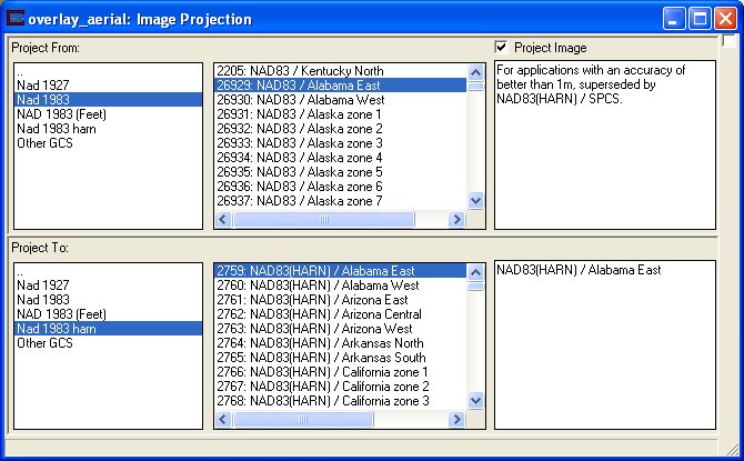
Image Projection Options: This toggle allows for the reprojection of the image. Each coordinate system is divided into either Geographic or Projected coordinate systems. The coordinate system types are navigated by selecting the appropriate system type in the far left window. When a general coordinate system has been selected a specific coordinate system can be selected from the center window. If there are any details regarding the selected specific coordinate system, they will appear in the text window on the right. A specific coordinate system must be selected both to project from and to project to, and then the Project Image toggle must be turned on.
Texture Bottom Surfaces: This toggle will tell the module to texture all surfaces whose normals are point downward.
Border/Wall Color: Since vertical surfaces (Walls) are not being textured this color button allows the color for these walls to be set.
Map Data: This toggle will cause the module to pass the first nodal data component through to the renderable object. NOTE: This will cause there to be a blending between the the nodal data color value and the image color.
Cull Back: This toggle when turned on will remove all faces that the user cannot see from the renderable object. This is useful for making a clearer picture when the transparency is not at one hundred percent.
Wall Visibility: This toggle when turned on will display the vertical surfaces (WALLS).
© 1994-2018 ctech.com