![]()
General Module Function
The data_math module is used to perform mathematical operations on nodal data fields and coordinates. Up to four fields can be input to data_math. Mathematical expressions can involve any or all of these input fields. If a data field contains more than one data component, you may select from any of them.
Nodal data input to each of the four ports is normally scalar, however if a vector data component is used, the values in the expression are automatically the magnitude of the vector (which is a scalar). If you want a particular component of a vector, insert an extract_scalar module before connecting a vector data component to data_math. The output is always a scalar. If a data field contains more than one data component, you may select from any of them. If the Data toggle is selected your modified data will be prepended to the original data components input to the A port. If it is off, the original data components input to the A port will pass through unaffected.
Module Input Ports
data_math has eight input ports.
There are four identical input ports that can accept any type of mesh, but the meshes must have the same cell types and number of nodes (i.e., they must have identical geometries). At least one input port must be used and up to four can be used. The first port is closest to the left and the ports are numbered sequentially in ascending order to the right.
Nodal data passed to ports one, two, three and four are referred to as Anx, Bnx, Cnx and Dnx (where x refers to the number of the data component) in the appropriate mathematical expression.
For example if you want to refer to third nodal data component of the first input you would use An2 (numbers start at zero) in the expression, if you want to refer to first nodal data component of the second input you should use Bn0 in the expression.
There are also four identical input ports that accept floating point numbers (variables). None of these are required to be used, but up to four can be used. The first of these ports is the fifth from the left and the ports are numbered sequentially in ascending order to the right. These variables are referred to as f1, f2, f3 and f4 in your mathematical expressions.
Module Output Ports
Data_math has six output ports. The first four output port (from the left) pass the four variables so they can be shared with other modules. The next port is the output mesh containing revised data and coordinates that are a result of the computation. The last (red) output port is renderable version of the output mesh.

Module Control Panel
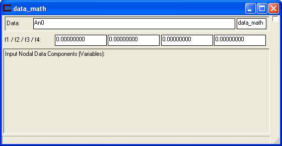
The control panel for data_math is shown in the figure above. The last type-in box in the Data row is for setting the data component name. This can make your network and application far more understandable, especially if you are dealing with multiple data_math modules and recombining them later. The other type-in boxes are for inputting mathematical expressions.
An example of an equation to blend the values of (interpolate between) two different fields having nodal data with a logarithmic distributions as f1 ranges from 1 to 0.0 is:
log10(pow(10,An0)*f1+pow(10,Bn0)*(1.0-f1))
You can also use
interplog(An0, Bn0,f1)
To perform interpolation between non-log processed data use:
An0 * f1 + Bn0 * (1.0-f1) OR interp(An0, Bn0,f1)
Pop-UpAvailable Mathematical Operators here.
Jump to a list of availableMathematical Operators
Related Modules
© 1994-2018 ctech.com