![]()
General Module Function
The seepage_velocity module is used to compute the vector groundwater flow field visualizations of the vector field.
The input data requirements for the seepage_velocity module are:
A Geo_Layer data component.
A Material_ID data component. If there is no Material_ID, we treat each layer as a separate material.
Layer 0 becomes material -1
Layer 1 becomes material -2
Layer 2 becomes material -3, etc.
Note: If you use Krig_3D to krige head data with geologic input (in Version 6.0 or later) your output will meet these criteria (provided you toggle on these data components under Kriging Parameters). Data kriged in older versions and saved as a UCD or netCDF will lack the Material_ID data component.
Module Input Ports
Seepage_velocity has two input ports. Data passed to the first port must be a 3D mesh with data representing heads and normally multiple geologic layers. The second port is the Z-Scale (exaggeration) parameter.
Module Output Ports
Seepage_velocity has two output ports. The first is the Z-Scale (exaggeration) parameter . The second port contains vector data representing x, y, and z components of seepage velocity. This data can be processed by the glyph, streamlines, or advector modules.

Module Control Panel
The control panel for seepage_velocity is shown in the figure above.
The seepage_velocity
Geologic Layer to Edit: allows you to select the geologic layer to assign conductivity and porosity properties.
Head Data Component radio button list displays all data components passed to seepage_velocity.
HeadUnits radio button list allows you to specify the units of your head data.
Coordinate Space: radio button list allows you to specify the units of your coordinate data.
Conductivity Units: radio button list allows you to choose the units for specifying the conductivity in all three (x, y, z) directions for each geologic layer. You can choose any units (regardless of your head and coordinate units) and the appropriate conversions will be made for you.
The Conductivity sliders (with type-in buttons) allow you to change the log10 of the x, y, & z conductivity. These specify log values because conductivities vary over many orders of magnitude. These update when the (Linear) type-ins are changed.
The Conductivity type-ins allow you to change the x, y, & z conductivity. These are actual values and update when the sliders are changed.
The Effective Porosity slider (with type-in buttons) allows you to change the value of effective porosity.
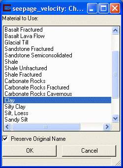
The Set Material button opens another window (shown below) where you can choose from many different geologic materials. When one of these materials is selected, all of the conductivity and the porosity values (and ranges in the sliders) are set for you. This allows you to quickly select nominal conductivity values based on the materials in your geologic layers.
The Run toggle determines if the module runs immediately when you change conductivity values. The default is off.
Material (#/Name): allows you to specify the material type if it is not specified in your geologic layers. This is only to help you assign proper conductivities.
Seepage_velocity component determines which data component is used to scale and rotate the seepage_velocity velocity vectors. The default selection is the first data component. The Map component radio button list also displays all data components passed to seepage_velocity. Map component determines which data component is used to color the seepage_velocity velocity vectors. By default, the first (0th) data component is selected.

Technical Details
Inherent in the solution of seepage velocity implemented in this module is the assumption that within each geologic layer/material the conductivities are uniform. Clearly, this will never be completely accurate, however we would contend that there is seldom if ever a better measure of the site conductivities (true conductivity tensor) than the site heads because head is far easier to measure. Furthermore, geologic materials can be deposited such that their conductivities are very complex and directional and most groundwater models (e.g. MODFLOW) do not provide a way to reflect this EVEN IF IT COULD BE MEASURED.
This approach allows users to quickly investigate the impact on flow paths due to changes in the conductivity assigned to each layer/material, BASED ON THE MEASURED/KRIGED HEAD DISTRIBUTION. Clearly, the more accurately the head is characterized the better.
At this point, we don't propose to provide a mechanism to account for conductivity variations within a geologic layer. We obviously cannot account for natural or artificial barriers (low conductivity regions) UNLESS they are represented by the geologic materials.
Our approach is:
Compute the true seepage velocity (Vx, Vy, Vz) at each node, by taking the gradient of (kriged) head (without any z-exaggeration) and multiplying each component of head gradient by the component of conductivity at that node (based on its material) (Kx, Ky, Kz) and dividing by the Effective Porosity for that material.
Vx = dH/dx * Kx / Ne
Vy = dH/dy * Ky / Ne
Vz = dH/dz * Kz / Ne
© 1994-2018 ctech.com