![]()
General Module Function
The volumetrics module is used to calculate the volumes and masses of soil, and chemicals in soils and ground water, within a user specified isosurface (surface of constant concentration), and set of geologic layers. The user inputs the units for the nodal properties, model coordinates, and the type of processing that has been applied to the nodal data values, specifies the subsetting level and soil and chemical properties to be used in the calculation, and the module performs an integration of both the soil volumes and chemical masses that are within the specified isosurface. The results of the integration are displayed in the EVS Status Window window, and in the module output window.
The volumetrics module computes volumes and masses of analytes using the following method:
A subset (plume) within the input grid is computed using the subsetting level specified in the volumetrics module
Each cell having any nodes within the subset is analyzed
The step above is limited to selected geologic units
The mass of analyte within the cell is integrated based on concentrations at all nodes (and computed cell division points)
The volumes and masses of all cells are summed
Centers of mass and eigenvectors are computed
For soil calculations the mass of analyte is directly computed from the computed mass of soil (e.g. mg/kg). This is affected by the soil density parameter.
For groundwater calculations, the mass of analyte (Chemical Mass) is computed by first determining the volume of water in each cell. This uses the porosity parameter and each individual cell's volume. From the cell's water volume, the mass of analyte is directly computed (e.g. mg/liter).
The volume of analyte (Chemical Volume) is computed from the Chemical Mass using the "Chem Density" parameter.
The volumetrics module will give more accurate results and should be used instead of the deprecated volume_integrate module.
Module Input Ports
The volumetrics module has seven input ports.
The first input port (the leftmost port) accepts a 3D data field.
The second input port is the explode distance of the model.
The third input port is the z exaggeration port.
The fourth port accepts a string as input; this string is then written to the output file if the Output Results File toggle has been selected.
The fifth input port takes a float value representing the subsetting level.
The sixth port takes a float value representing the date.
The seventh port takes an integer as its input; this integer causes the module to run when changed.
Module Output Ports
volumetrics has two output ports.
The first port (the leftmost) outputs a float representing the subsetting level.
The second port outputs the volume of the 3D field as a float.
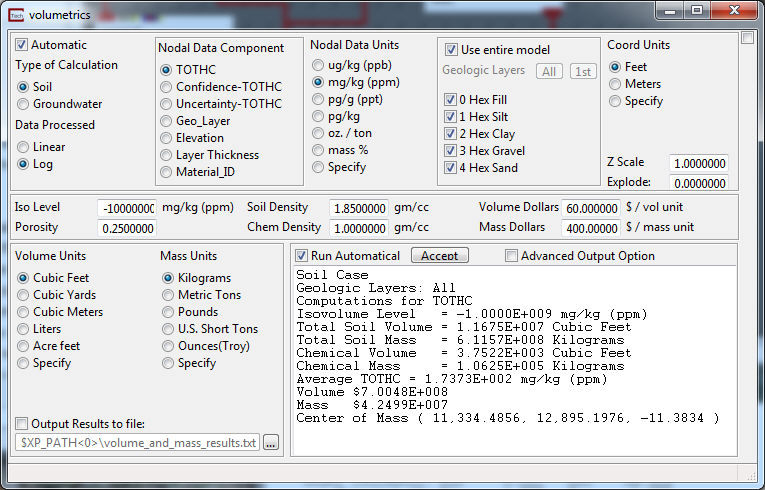
Module Control Panel
The control panel for volumetrics is shown above.
The Automatic toggle will try to automatically determine the following options based upon the model data that is in the input field: Type of Calculation(Soil or Groundwater); Data processed, this is based upon the selected Node Data; Node Data Units, once again dependent on the selected Nodal Data Component; and Coordinate Units. To change any of these values the automatic toggle should be turned off.
The Type of Calculation toggle changes the type of nodal data units that are available for selection.
The Data Processed radio list is used to specify whether the input data field has been processed to compute the Log 10 of the nodal values by Krig_3D or the module that is supplying the data to volumetrics. The default value is on, which means that Log 10 processing has been completed. Note that most analyte (e.g. chemistry) related data are log processed, while other types of data are not. If the user is not sure which processing has been completed, the Statistics module can be used to examine whether negative values that resemble log 10 data are present in the data set. When Log 10 processed data is passed to volumetrics, it exponentiates the nodal values in the data file, and completes the integration within the isosurface assuming that the data are exponentially distributed. This algorithm essentially returns the data to a normal distribution to provide accurate volumetrics estimates.
The Nodal Data Component lists the nodal data components that can be used to determine volumetrics.
The Nodal Data Units radio list allows the user to select the units of the Nodal Data Component. These options can change depending on the selection of the Type of Calculation. The last option in the list is Specify, as shown below, this allows the user to specify their own units for calculation.

NOTE: The Unit Ratio is the ratio of the user specified units to the units we use for calculation. For example, the units we use for the Nodal Data Component in our calculations are grams/grams. If you wanted to use the units of mg/kg (ppm) you would need to find the ratio to convert the units which is in this case .001/1000 or .000001.
The Geologic Layers panel has a toggle which is dominant and other selectors:
The layer selection list allows the user to select which of the geologic layers the volumes and masses will be calculated in. The layer number for which the estimates are made is printed in the EVS Console Window, along with the results.
NOTE: There are two different ways to perform volume calculations on individual geologic layers.
1) IF you have not used a plume_volume (or similar) module upstream of volumetrics you can use the Geologic Layers selection list allows you to choose the cell sets (geologic layers) that you want to perform computations on. Since geologic layers are segregated into "cell sets" this works only if there are no upstream modules LIKE plume_volume, which affects the cell sets.
If you use plume_volume upstream, it creates a single cell set for all hexahedron (hex) cells and another for all tetrahedron (tet) cells. This merges all geologic layers and makes it impossible to perform geologic layer subsetting INSIDE of volumetrics.
2) However, if you use the Explode_and_Scale or a select_cells module UPSTREAM of plume_volume you can pick one or more geologic layers that will be included in your volume calculations. In this case, make sure all cell sets (hex and tet) are selected. In other words, perform your computations on everything.
When there are HEX and TET cell sets, you need BOTH. The hex cells are those cells in your grid that are completely within your threshold (subsetting level). These WHOLE cells are output from plume_volume unchanged EXCEPT that they are all lumped together in a single cell_set. Any cells that are not COMPLETELY inside the subsetting level are cut into smaller pieces that are completely inside. Those smaller pieces are composed of Tetrahedrons. All of the tetrahedrons are output in a single TET cell set.
Remember, you don't get the correct volume unless you include both Hex and Tet cell sets.
The Coord Units radio list is used to select the unit of measurement for the X, Y, and Z coordinates of the model data. The user should be certain of the nodal and coordinate units selected, as obviously, the outputs of the calculations are significantly affected by the units of the data. For the Specified Ratio the users input units need to be converted to Liters.
The Z Scale input field specifies the value of z exaggeration and is used to unscale the model for the purpose of calculations.
The Explode input field specifies the value the model has been exploded by and is used to unexplode the model for the purpose of calculations.
The subsetting level input field specifies the value in user units of the isosurface within which the volumetrics estimates will be completed. Note that the unit's text following the subsetting level input field will change to be consistent with the Nodal Data Units radio button selected, to remind the user what data units are being used.
The Soil Density and Porosity input fields allow the user to input the properties of the soil matrix in which the chemicals reside. Note that if the mass of chemicals in a combined soil and ground water plume are to be estimated, one of the geologic layers should be set up to have a boundary within it that corresponds to the water table position. In essence, this will create two layers out of one geologic unit that can be used to separate the soil domain from the ground water domain. The user can then choose the appropriate Nodal Data Units for each layer in the two domains, and obtain volumetrics estimates by summing the results in individual layers. There are several other alternative methods for completed volumetrics estimates in continuous soil and ground water plumes, which involve either setting up separate soil and ground water models, or using the Field Math module to remove and include specified areas of the domains.
The Chem Density input field allows the user to input the density of the chemical constituent for which mass estimates are being completed. Note that this value is used to calculate the volume of chemical in the specified isosurface, as the mass units are calculated directly from the nodal data.
The Volume Dollars type in is used along with the total volume of the chemical to indicate the cost of the removal of the chemical.
The Mass Dollars type in is used, along with the total chemical mass, to determine the value of the chemical mass.
Volume Units is used to select which units the volume should be calculated in. For the Specified Unit Ratio the units to convert to are liters. For example if your units were Cubic Meters the ratio would be 1000.
Mass Units is used to select which units the mass should be calculated in. For the Specified Unit Ratio the units to convert to are Kilograms.
The Output Results File toggle causes volume_and_mass to write a file to the ctech folder (volume_and_mass_results.txt) that contains all volumetrics information in a format suitable for input to programs like Excel (tab delimited .txt file). This file is written to in an append mode. It will grow in size as you use volumetrics. You should delete or move the file when you're done with it.
The Run Automatically toggle, when selected, causes the module to run as soon as any of the input parameters have changed. When not selected the accept button must be pushed for the module to run.
PRO and MVS only
For PRO and MVS users there is an advanced window that can be opened by checking the Advanced Output Options toggle.

The advance panel provides many capabilities including Spatial Moment Analysis.
Spatial Moment Analysis involves computing the zeroth, first, and second moments of a plume to provide measures of the mass, location of the center of mass, and spread of the plume.
The zeroth moment is a mass estimate for each sample event and COC. The estimated mass is used to evaluate the change in total mass of the plume over time.
The first moment estimates the center of mass of the plume (as coordinates Xc , Yc, & Zc).
The second moment indicates the spread of the contaminant about the center of mass (sxx,syy andszz), or the distance of contamination from the center of mass. This is somewhat analogous to the standard deviation of the plume along three orthogonal axes represented as an ellipsoid created using the eigenvalues as the ellipsoid major and minor axes, and the eigenvectors to orient the ellipsoid. The orientation of the ellipsoid is aligned with the primary axis of the plume (not the coordinate axes).
The Second Moment ellipsoid represents the spread of the plume in the x, y and z directions. Freyberg (1986) describes the second moment about the center of mass as the spatial covariance tensor.
The components of the covariance tensor are indicative of the spreading of the contaminant plume about the center of mass. The values of sxx,syy andszz represent the axes of the covariance ellipsoid. The volumetrics module provides a scaling parameter that allows you to view the ellipsoid corresponding to the one-sigma (default) or higher sigma (higher confidence) representation of the contaminant spread.
The Water Density type in window allows the user to specify the density of water. The default of 0.9999720 g/mL is the Density of Water at 4.5 degrees Celsius.
The Refinement Cycles slider specifies how finely each element will be subdivided to perform the integration. The default value is 0, which provides the fastest computation time, and resulting volumetrics estimates that are a good first approximation. Generally, the number of refinement cycles should be set to a value between 1 and 4, and the user should experiment with increasing the refinement cycles until subsequent calculations show a change that is insignificant to the problem at hand.
The Output Filetype radio list is used to select the format of the output file. The default is a tab spaced single line output, the second choice will format the output the same as the display window, and the third option will format the output separated by tabs on multiple lines. Changing these options will not cause the module to run, you must hit accept or change an input value for the module to run.
Overwrite causes the output file to be overwritten instead of appended to. This toggle will only be selected for one run and then will unselect itself and begin appending again, unless it is rechecked. Selecting this toggle will not cause the module to run, you must hit accept or change an input value for the module to run.
The Date type in allows you to set the date, which is output only in the Tabbed Multi-Line file.
The Display Mass Centerline allows you turn on and off the lines lying along the Major, Minor, and Intermediate Eigenvectors. These vectors represent the second moment of mass, and by default have chemical data mapped to them. These lines are of the same orientation as the second moment ellipse but they stretch only to the extents of the model. To output these lines the Export Results button must be pushed.
The Segments type in allows you to control the number of segments making up each line, the larger the number of segments the closer the node data along the line will match the node data of the model, but at the cost of speed.
The Color Lines by Axis toggle strips the node data from the lines leaving them colored by the axis the represent.
EllipsoidDivisions is an integer value determines the number of faces used to approximate the analytically smooth ellipsoid. The higher the resolution the smoother the ellipsoid. The Export Results button must be used to have an output port for the ellipsoid.
EllipsoidScale is a scaling factor for the second moment ellipsoid. A value of 1.0 (default) is analogous to one-sigma (67%) statistical confidence. Higher values would provide an indication of the size of the eigenvalues with a higher statistical confidence.
The Export Results button adds an additional seven output ports to the original two for a total of nine output ports.
![]()
The first port (the leftmost one) exports a float representing the subsetting level.
The second port exports a float representing the Soil Volume.
The third port exports a float representing the Soil Mass.
The fourth port exports a float representing the Chemical Volume.
The fifth port exports a float representing the Chemical Mass.
The sixth port exports a field representing the Ellipse of the second moment of mass.
The seventh port exports a renderable object representing the Ellipse of the second moment of mass.
The eight port exports a field representing the Mass Centerlines of the second moment of mass.
The ninth port exports a renderable object representing the Mass Centerlines of the second moment of mass.
© 1994-2018 ctech.com