Geologic Hierarchy
C Tech's original method for 3D geologic modeling utilizes one of two different ASCII file formats which contain "interpreted" geologic information. These two file formats both describe points on each geologic surface (ground surface and bottom of each geologic layer), based on the assumption of a geologic hierarchy. Simply stated, layer hierarchy requires that all geologic layers throughout the domain be ordered from top to bottom and that a consistent hierarchy be used for all borings. At first, it may not seem possible for a uniform layer hierarchy to be applicable for all borings. Layers often pinch out or exist as localized lenses. Also layers may be continuous in one portion of the domain, but are split by another layer in other portions of the domain. However, all of these scenarios and many others can be easily modeled using a hierarchical approach.

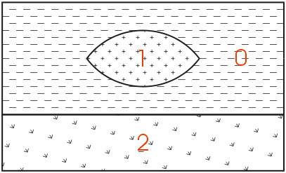
The easiest way to describe geologic hierarchy is with an example. Consider the example above of a clay lens in sand with gravel below.
Imagine borings on the left and right sides of the domain and one in the center. Those outside the center would not detect the clay lens. On the sides, it appears that there are only two layers in the hierarchy, but in the middle there are three materials and four layers.
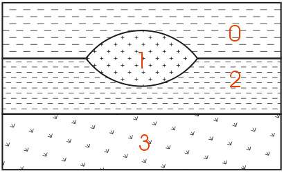
EVS's & MVS's hierarchical geologic modeling approach accommodates the clay lens by treating every layer as a sedimentary layer. Because we can accommodate "pinching out" layers (making the thickness of layers ZERO) we are able to produce most geologic structures with this approach. Geologic layer hierarchy requires that we treat this domain as 4 geologic layers. These layers would be Upper Sand (0), Clay (1), Lower Sand (2) and Gravel (3).

If desired, both Upper and Lower Sand can have identical colors or hatching patterns in the final output.
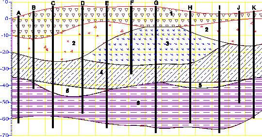
For those sites that can be described using the above method, it remains the best approach for building a 3D geologic model. Each layer has smooth boundaries and the layers (by nature of hierarchy) can be exploded apart to reveal the individual layer surface features. In the above example, the numbers represent the layer numbers for this site (even though layers 1 and 3 are both sand). Two examples of much more complex sites that are best described by this original approach are shown below.
Geologic Example: Sedimentary Layers and Lenses

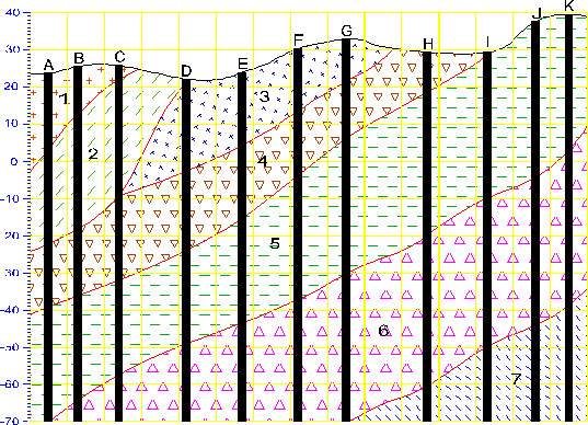
Geology Example & Figure: Outcrop of Dipping Strata
EVS is not limited to sedimentary layers or lenses. The figure below shows a cross-section through an outcrop of dipping geologic strata. EVS can easily model the layers truncating on the top ground surface.

© 1994-2018 ctech.com