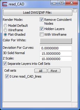
We will now add a .DXF file overlay on the model. Adding a .DXF file provides familiar spatial references to the model results.
To add a CAD file to the model:
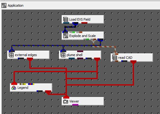
1. Instance the read_CAD module. This module is found in the File module library.
2. Connect up its output port to the input port on the viewer and connect the grey-brown (z-scale) port from Explode_and_Scale..
3. Open the read_CAD control panel and select the Load DWG/DXF File button. Change to the \ctech\data\modeling\ directory and choose the file multi_layer_modflow_site_map.dxf. This file was created using the surf_map module to drape the constant elevation lines onto the top geologic surface. When it was created, the surface was exaggerated by a scale factor of 1. The grey-brown port will cause the z coordinates to be properly scale to lie on the topmost surface. The draped DXF file is also much larger than the original file because each simple straight line is broken into a complex polyline which must follow the contours of the underlying surface.

Set your view (Az-El) parameters to Scale = 1.60, Elevation = 25, and Azimuth = 150. The image in the viewer now shows an volumetric subset of the drawdown greater than .3 foot and an overlay of the site basemap.
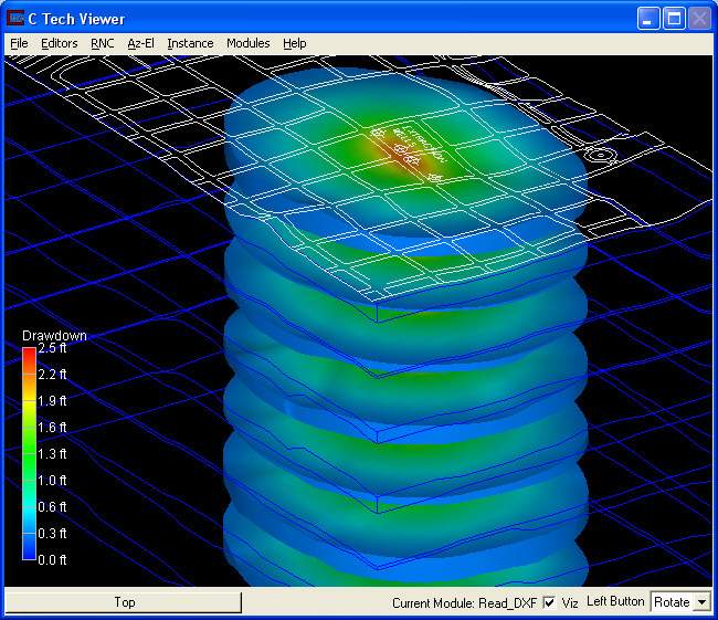
There is just one thing a bit wrong here. Note that the lines of the DXF may seem a bit broken or erratic in the area of the drawdown (plume). This results from the fact that our DXF lines and the plume surface have the same z-coordinates. These objects are coincident in space. When this happens (or nearly happens) the rendering of objects can become ambiguous. The Viewer doesn't know which object is closer to our eye and should be drawn and which should be masked by the other.
C Tech's viewer includes an object setting that can address this issue. It is called jitter. If two objects are coincident but one has a higher jitter, it is preferentially drawn. We will set the jitter of the DXF lines higher.
To do this, select the read_CAD object. The quickest way is to use the Alt+Left mouse button and click directly on some of the lines. If you do it right, the button in the lower left corner of the Viewer should change to say "read_CAD." You can also use the Object_Selector, just as we did earlier.
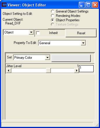
Now, from the Viewer, choose Editors->Object->Advanced Settings Select Object Properties at the top of the Object Editor window, and then select General in PropertytoEdit. At the bottom of this window you will see a Jitter Level slider. Set it to 1 (it should have been zero). As soon as you do this, the lines should become clearer. If you experiment with jitter you'll see that setting it to -1 will make the lines completely disappear where they overlap the plume. We'll leave it at 1.
The current application should match:
© 1994-2018 ctech.com