![]()
General Module Function
This module has been deprecated and replaced by the read_CAD module.
The Read_DXF module will read an industry standard CAD DXF format graphics file, and place the graphic entities into the EVS viewer. This module provides the user with the capability to integrate site plans, buildings, and other features into the EVS visualization, to provide a frame of reference for understanding the three dimensional relationships between the site features, and characteristics of geologic, hydrologic, and chemical features. The DXF entities are treated as three dimensional objects, which provides the user with a lot of flexibility in the placement of DXF objects in relation to EVS objects in the visualization. The surfmap module allows the user to drape DXF line-type entities (not 3D-Faces) onto three dimensional surfaces. Read_DXF supports the following DXF entities:
1) lines,
2) polylines,
3) arcs,
4) circles,
5) simplex text, and
When creating a DXF from AutoCAD for import to EVS, the user should specify that the "Entities" be exported when first prompted for the number of decimal places (this will be an option In the ACAD command line). After selecting the objects to include in the DXF, the user can specify only the number of decimal places needed to adequately place the object in the drawing (2 decimal places is usually sufficient). Including many decimal places in a DXF drawing increases the size of the file and the time required to read it into EVS with no tangible benefit. Also note that although Read_DXF can handle large DXF files, a lot of other information will typically be displayed when using EVS, and thus the simplest DXF overlay that conveys the required information generally produces the best displays.
Note: the default rendering mode is outline mode = "off" for this module. Surfaces no longer show cell boundary lines, but lines are still visible. To view outlines of surfaces, set outline mode equal to "on".
Module Input Ports
The Read DXF module is shown above. Read DXF has one input port for the Z Scale.
Module Output Ports
The first (left) port outputs the Z Scale.
The second port outputs a typical data field which can be input to surfmap, external edges and/or any of the Subsetting and Processing modules which have the same color port.
The right port outputs a renderable geometry, and can only be connected to the viewer.

Module Control Panel
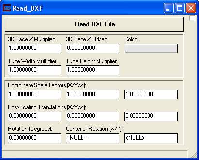
The parameter input panel for Read DXF is shown above.
Clicking the Read DXF File button opens a standard windows style file browser which allows the user to select a DXF file from a specified directory. There are many different types of entities, and some differences in formats, that can be present in DXF files. EVS is currently able to process the common types of graphic entities such as lines, polylines, circles, and text. However, the user should be aware that some programs which produce DXF "compatible" files, may not actually be 100% compatible with the AutoCAD DXF format standard, and therefore may not import correctly to EVS. The module runs as soon as you read the file.
The 3DFace Z Multiplier and Z Offset fields allow the user to scale the vertices of 3DFACE DXF entities, and offset their position in the Z axis relative to the original vertices. Note that these parameters only need to be used when special placing of 3D FACE entities is desired. The offset parameter must consider the scaling multiplier as described above for translation factors. These factors are applied after the primary scaling and translation factors listed above.
The color of the DXF entities which do not have assigned (DXF) entity colors are controlled by Color button. All entities that do not have set colors in the DXF receive the same color.
The Coordinate Scale Factors type-ins allow the user to scale the coordinates of the DXF entities in the X, Y, and Z axes. The default scale factors are 1.0, but the user can input any positive scaling values, by which the coordinates of the respective axes will be multiplied. The scale factors must be used to correctly place the DXF entities when Z exaggeration or other scale factors are being applied to the kriged data distributions to produce effective visualizations. In this case, the scale factor should be noted from the Explode and Scale or Kriging parameter input panels, and an equivalent, or nearly equivalent factor should be applied in the Read DXF scale factors (note that the scale factors usually only affect the Z axis scaling).
The Post Scaling Translations data input fields allow the user to translate the DXF entities in all three axes for placement in the visualization. These factors are useful if different coordinate systems are being used for the DXF file, and the geologic or hydrologic data. Note that if Coordinate Scale Factors are being applied, then the user must enter translation parameters that consider the scaling parameters. As an example, if a Coordinate Scale Factor of 10 is specified for the Z axis, and the user also enters a translation factor of 10, then the DXF entities will actually be translated 100 original units in the Z Axis.
The Rotation type-in rotates the entire output about the Z axis by the specified amount in degrees. The Center ofRotation(X/Y) type-ins determine the center for the rotation.
Explanations of the various parameter settings and their effects on the visualization are presented in Workbook 2.
Coloring DXF lines using the Viewer
Coloring lines from a DXF file can now be accomplished by first selecting the Read_DXF object in the Viewer, then choose Editors --> Object Editors. Within this panel choose Object Properties AND Type General. Then in the lower Object pull down list change the selection from primary to secondary. Now, changing the line color is possible via either HSV dials or sliders.
© 1994-2018 ctech.com