General Module Function
The read_CAD module will read all versions of AutoCAD DWG and DXF files.
This module provides the user with the capability to integrate site plans, buildings, and other 2D or 3D features into the EVS visualization, to provide a frame of reference for understanding the three dimensional relationships between the site features, and characteristics of geologic, hydrologic, and chemical features. The drawing entities are treated as three dimensional objects, which provides the user with a lot of flexibility in the placement of DXF objects in relation to EVS objects in the visualization. The surfmap and geologic_surfmap modules allow the user to drape DXF line-type entities (not 3D-Faces) onto three dimensional surfaces.
Virtually all AutoCAD object types are supported including points, lines (of all types), 3D surface objects and 3D volumetric objects.
AutoCAD drawings can be drawn in model space (MSPACE) or paper space (PSPACE). Drawings in paper space have a defined viewport which has coordinates near the origin. When read into EVS this creates objects which are far from your true model coordinates. For this reason, all drawings for use in our software should be in model space.
Polylines with WIDTH are converted by Read_CAD into triangle strips of the specified width. As you zoom in on polylines with width, the apparent width will change, whereas the apparent width of lines DOES NOT change. However, once they are triangles, they DO NOT define a closed area and therefore would not work with triangulate_polygons.
Module Input Ports
The read_CAD module is shown above. read_CAD has one input port for the Z Scale.
Module Output Ports
The first (left) port outputs the Z Scale.
The second port outputs a typical data field which can be input to surfmap, external edges and/or any of the Subsetting and Processing modules which have the same color port.
The right port outputs a renderable geometry, and can only be connected to the viewer.
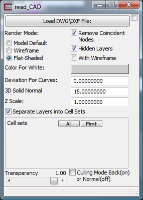
Module Control Panel
The parameter input panel for Read DXF is shown above.
Clicking the Load DWG\DXF File button opens a standard windows style file browser which allows the user to select an AutoCAD DWG or DXF file from a specified directory. The module runs as soon as you read the file.
The Render Mode options allow you to choose how the CAD data will be rendered. The options and their consequences are:
a)Model Default:Newer versions of AutoCAD can save the mode by which surface element are diplayed. This will honor that setting
b) Wireframe displays the surface objects as a wireframe display
c) Flat-Shadeddisplays surface objects as flat-shaded surface elements
The With Wireframe toggle outlines surfaces. It is equivalent to setting Line Rendering to "regular"
The Remove Coincident Nodes toggle causes the reader to process the data, removing coincident nodes. This takes longer to process but creates a smaller more efficient representation of your CAD data.
TheDeviation for Curvesfieldallows the user to specify the accuracy with which analytical curves (arcs, circles) are displayed. The default value of 0.0 employs an expert system algorithm to determine a reasonable value based on the overall size of your CAD model. We recommend that you use this value, especially the first time a file is read.
The Z Scale field allows the user to scale the Z coordinates. The default scale factor is 1.0, but the user can input any value, by which the Z coordinates will be multiplied. The scale factor must be used to correctly place the entities when Z exaggeration or other scale factors are being applied to the kriged data distributions to produce effective visualizations. In this case, the scale factor should normally be input from the Explode and Scale module, and an equivalent, or nearly equivalent factor should be applied in the Read DXF scale factors (note that the scale factors usually only affect the Z axis scaling).
The Separate Layers into Cell Sets toggle causes each layer in the CAD file to be output as a separate cell set in EVS.
The Cell Sets subpanel allows you to control visibility of cell sets in CAD file. When the above toggle is on, each layer may be represented by up to two cell sets, since each cell set can only contain a single type of cell such as points, lines, triangles, etc. All objects are represented as lines or faces in EVS. Points are represented as zero length lines. Volumetric CAD objects are output as the external faces of the object, not as a true 3D volumetric representation.
Cell set visibility can be toggled on-off in this panel.
The Culling Mode toggle controls whether back facing surface are visible. Generally you will want this ON when making the object(s) transparent.
The Transparency slider determines the opacity of the objects.
Related Modules
-> write_CAD
© 1994-2018 ctech.com