![]()
This is a deprecated module that has been supplanted by overlay_aerial
General Module Function
Thetexture_mapmodule(available only in EVS-PRO and MVS),replaces the texture_mesh and texture_mesh_set modules which have now been deprecated as of version 6.5. Working in conjunction with the enhancements to Read_Image or the new georeference_image module, it provides a much simpler, cleaner approach to texture mapping. It also supports transparency in the input images, allowing partially transparent textures.
texture_map is an enhancement to texture_mesh and texture_mesh_set in that it provides a means to project (texture map) images onto surfaces which are larger or smaller than the desired mapped extents. For example, the user may map a "postage stamp sized" aerial photo onto a very large topographic surface, or conversely, the user may project extents for an aerial photo that are outside the extents of the surface or object that the photo is projected onto.
It will handle ANY world file or GCP file (read automatically by Read_Image), including ones with arbitrary rotations and shears or higher order polynomial corrections (which can be created by the Georeference_Image utility).
Additionally, this module can accept data from world files (like TIF or BMP World Files) that provide georeferencing information for an image. The world file data is passed automatically from Read_Image. This will set the extents for mapping the image for you to eliminate potential errors and speed processing.
Module Input Ports
texture_map has two input ports. The left input port should be surface data (such as 3DFACES) from the Read_DXF module or a geologic surface, and the right input port should be an image from the Read_Image module.
Module Output Ports
texture_map has two output ports. The first output port (closest to the left) outputs an EVS field containing the texture mapped surfaces. The second port outputs a renderable version directly to the Viewer.

Module Control Panel
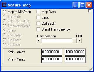
The control panel for texture_map is shown in the figure above.
The Map Data toggle displays the underlying nodal data before texture mapping. If the input surfaces has nodal data, the texture map will be overlayed on colored surfaces. This is generally not desirable.
The Lines toggle determines whether lines are included in the output. The lines toggle will allow lines (such as a bounding box matching the image spatial extents) to be displayed.
Cull Back - A toggle for use with the transparency option. This feature may produce a better transparency when a surface is shown with other transparent surfaces, or if the same surface has high relief and is causing a confusing visualization. It's use will require experimentation to determine if it is appropriate.
BlendTransparency - A toggle to allow for transparent regions based on the alpha channel in your image.
Transparency - A slider for adjusting the opacity of the texture mapped image. A value of 1.00 is completely opaque and a value of 0.00 is completely invisible.
Modes: There are 8 different texture mapping modes as follows:
1) Map to Min/Max - Map image to the min/max extents of the input surface, or a user-defined value (can be typed into texture map directly).
2) Translate - Translate the image. Only requires a single GCP. No rotation or scaling is performed.
3) 2 pt: Trans./Rot. - Translate, Scale, and rotate the image. The image scaling is always the same in X&Y. Only a valid option if you have 2 GCPs. Good option if you only know 2 GCP points, and they are co-linear or near co-linear.
4) Translate/Scale - Translate and scale the image. Scale in X and Y are not the same. This keeps the image orthorectified. Can be used with 2 or more GCP points.
5) Affine - Perform a full affine transformation (1st order transformation) on the image. Requires a world file or 3 or more GCP points (from a gcp file). This is the default option which can be fully described with a World File.
6) 2nd Order - Perform a 2nd order polynomial transformation. This requires 6 or more GCP points (from a gcp file). It will map straight lines in the image into arcs. Allows an image that was georeferenced previously into LAT/LON coordinates to be "straightened" out and handled correctly. This can also be used to adjust for minor problems in the image due to topography. This option cannot be described with a World File because it uses a second order polynomial with more terms than are available in a world file. It requires the use of a GCP file.
7) 3rd Order - Perform a 3rd order polynomial transformation. Requires 10 or more GCP points. Allows you to adjust for drift in the image, "wedge" shaped photography, and more.
8) 4th Order - Perform a 4th order polynomial transformation. Requires 15 or more GCP points. Allows adjustments to be made where different portions of the image move in opposite directions. Requires many GCP points to use effectively.
Xmin - Xmax - Type-ins for the minimum and maximum X extents of the texture mapped image. As noted above, this can be anywhere inside or outside the extents of the surface being mapped onto.
Ymin - Ymax - Type-ins for the minimum and maximum Y extents of the texture mapped image.
© 1994-2018 ctech.com