General Module Function
The Explode and Scale module is used to separate (or explode) and apply a scaling factor to the vertical dimension (z-coordinate) of geologic layers in a model. Explode and Scale can also translate the geologic layers in the z-coordinate direction, and can control the visibility of individual geologic layers.
Module Input Ports
Explode and Scale has three input ports.
The first (leftmost) accepts mesh and nodal data from Krig_3D, Read_UCD and 3D_Geology_Map. Input to this port must contain a UCD mesh and specific nodal data components.
The second input port accepts an explode factor, which specifies the distance that the geologic layer bottoms and tops will be separated.
The third input port (furthest right) accepts a scaling factor, which specifies the multiplication factor that the z-coordinates of the mesh nodes will be scaled by.
Note that the explode and scale factors can be passed to Explode_and_Scale, (from another Explode_and_Scale nodule) or the user can input them in the control panel if no factors are being applied to other modules in the network. Explode_and_Scale will report errors if the input data does not have geologic layer data for the fourth component (#3, #0 is first) and elevation data for the fifth component.
Module Output Ports
Explode_and_Scale has three output ports.
The first (closest to the left) outputs the explode factor that was input or passed to the module
The second (middle) port outputs the scaling factor. The first two ports can be connected to the post_samples and other Explode_and_Scale modules, to provide the factors being used by Explode_and_Scale.
The third output port passes the exploded and scaled data field, for input to other modules such as Generate Axes and Geologic Surface.
Remember that the values of the nodal data components are not affected by Explode_and_Scale, only the z-coordinates of the node positions are.
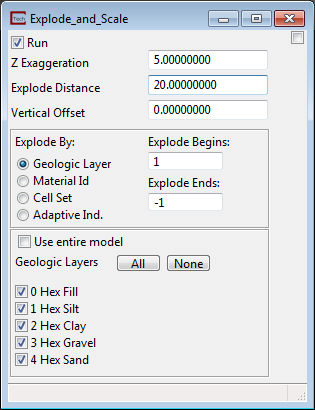
Module Control Panel
The control panel of Explode and Scale is shown in the figure above. There are five fields available for type in input:
Z Exaggeration is the scaling factor for vertical (z) coordinates. This value reflects a multiplication factor of the layer thickness. For example, a layer that is 10 feet thick that is subjected to a z- exaggeration value of 4, will appear 40 feet thick in the viewer.
Explode Distance is the distance between exploded layers, cell sets or materials. For example, an explode distance of 20 will separate each geologic layer by 20 feet from the layer above it and the layer below it. Note that the explode distance incorporates the scale factor, so that if a scaling factor of 5 is specified for a 10 foot thick layer to which an explode factor of 20 is applied, the geologic layers will be separated by 100 feet.
Vertical Offset translates your entire model in Z by the value input multiplied by the Z Exaggeration. This is useful if you want to move your model to avoid having coincident objects.
Explode Begins determines the first layer or material that will be exploded.
Explode Ends sets the last layer/material which will be exploded. This value defaults to -1 which will explode all remaining layers or materials.
Explode By: determines what information is used to explode the layers or materials.
The default is Geologic_Layer which is a nodal data component that should be present with any hierarchical geologic model created in EVS/MVS. For this type of model Geologic_Layer is always ZERO (0) for the uppermost layer and counts down to your lowest layer. If you have 5 geologic layers, the Geologic_Layer values will range from 0 to 4.
Material_ID is a nodal data component that should be present with any hierarchical geologic model created in EVS/MVS. For this type of model Material_IDs are values which you have specified in your .GEO or .GMF file. Exploding by Material_ID allows you to keep geologic layers which represent the same material grouped together.
The Cell Set option allows you to explode by the Cell Set number. For typical hierarchical geologic models created in EVS/MVS, exploding by Cell Set should be identical to exploding by Geologic_Layer. However, there are many occasions where the cell sets are quite different than the Geologic_Layer values.
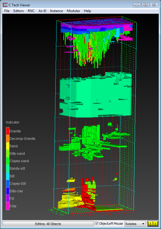
The Adaptive Ind. option is to be used only with Adaptive Indicator Kriged geologic models. These models have a cell data component called Indicator which corresponds to integer values assigned to material regions. Unlike models created with Indicator_Geology (which have only one cell set) models created with adaptive_indicator_krig have multiple cell sets corresponding to the Indicator values assigned to material regions in the PGF input file. For these models you should not try to explode by Cell Set since each material region will be represented by two cell sets; one of HEX cells and one of TET cells.
Under the Geologic Layers heading:
Issues and Notes:
Z Exaggeration and Explode Distance are values for the entire data set. Every geologic layer in the data will be exaggerated and exploded the same amount.
Indicator Geology models cannot be exploded since there is only one cell set with shared nodes between different materials.
Adaptive Indicator Geology models generally must have an Explode Distance which is greater than the total vertical extent of the unexploded model.
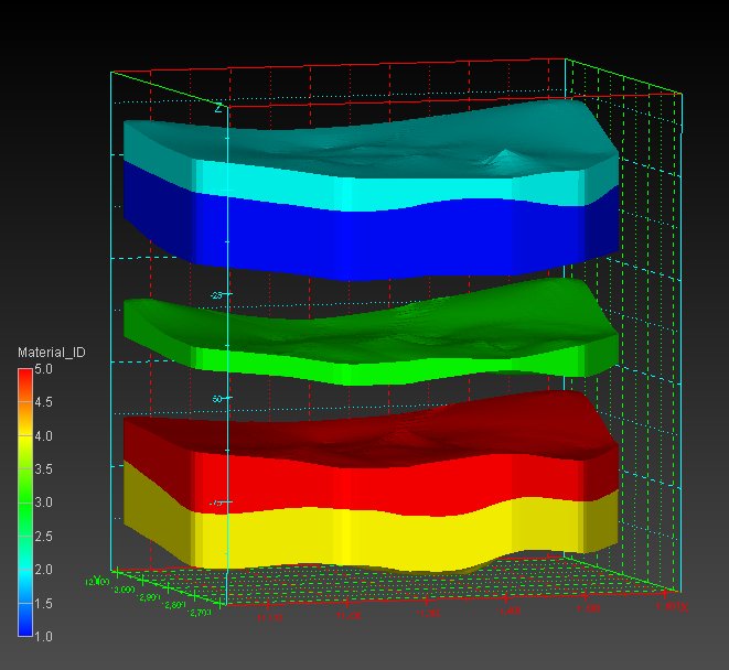
The example below shows the Viewer for the Explode_and_Scale settings show above with the data set used in Workbook 4.
The images below show the Explode_and_Scale window and resulting model for a 10 material (material IDs 0 to 9) Adaptive Indicator Geology model.
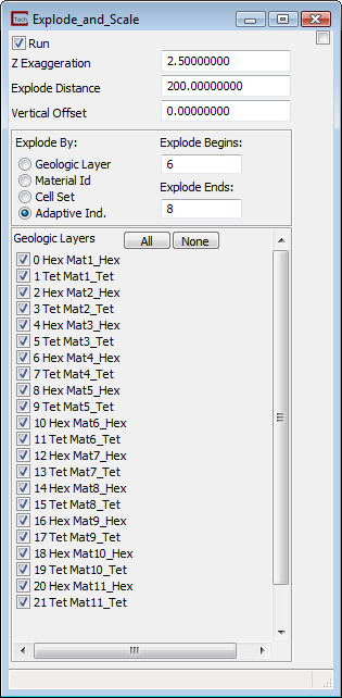
Since we are exploding from Indicator 6 through 8, the materials 0 through 5 are not exploded, materials 6 & 7 are separate and materials 8 through 11 are grouped together at the bottom. The model is in 4 groups, two more groups than the Explode Ends minus Explode Begins.
© 1994-2018 ctech.com