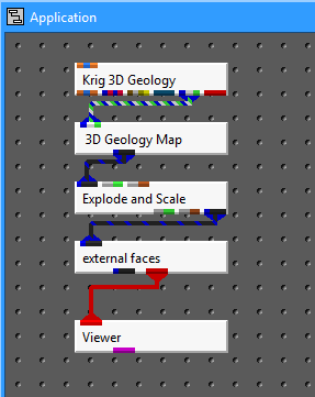
Delete the Geologic Surface module and instance 3D_Geology_Map (in Processing Sublibrary) and connect the tri-colored output port on Krig_3D_Geology to its matching input port.
Instance Explode_and_Scale (top of Display) and external_faces (top of Subsetting). Connect the blue/black output of 3D_Geology_Map to Explode_and_Scale and connect its blue/black output to external_faces. Connect the red output of external_faces to the Viewer to create the following network.

Connecting 3D_Geology_Map should result in the following message being printed to the console:
_3D_Geology_Map:
Layer Thickness: Min 2.260 Max 20.420
X Coordinates: Min 11054.905 Max 11617.664
Y Coordinates: Min 12679.596 Max 13121.776
Geo_Layer: Min 0.000 Max 4.000
Elevation: Min -55.945 Max 11.407
Material_ID: Min 1.000 Max 5.000
Depth: Min 0.000 Max 59.395
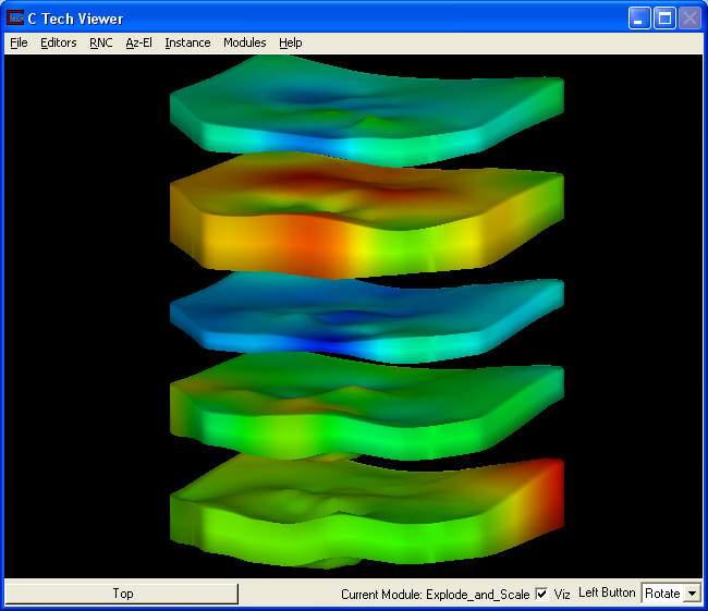
This data provides the ranges for all of the nodal parameters associated with the solid model. Since Layer Thickness is the first parameter, the model is colored according to layer thickness by default. Note that this model has no layers with zero thickness (i.e. no pinched out areas).
The Modules list now has a pull-down command to access the user interface for Krig_3D_Geology, _3D_Geology_Map, external_faces, and Explode_and_Scale. 3D_Geology_Map produces a solid model using the geologic surface data created by Krig_3D_Geology. Its interface has options for proportional gridding and grid resolution in the Z direction. You can use Explode_and_Scale to adjust the exaggeration and explode distance of the layers. For now, leave the default values.
Click on Az-El on the Viewer menu and choose .70 Scale, 10 degree Elevation and 150 Azimuth to get a view of the solid model. Once you've done this, hit the multi-colored button (Reset/Normalize/Center) in the Az-El panel. You should have the following view in your Viewer.

Open the user interface for external_faces in the Modules pull-down menu. You can choose which of the nodal data components is used to color the model.
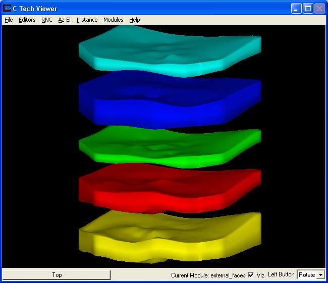
If you choose Material_ID as the Data component you will be coloring according to the geologic material number on line 3 of the .geo file. The order of those numbers were 2, 1, 3, 5 and 4 which gives layers colored as:

To obtain more appropriate geologic colors we must edit the datamap of external_faces. For instructions on how to do this see the Datamap_Editor.
© 1994-2018 ctech.com