![]()
General Module Function
The glyph module is used to place geometric objects (glyphs) at nodal locations. The glyphs can be scaled, rotated and colored based on the input data. If the input data is a vector, the glyph can be scaled and rotated to represent the direction and absolute magnitude of the vector field. In a scalar data field, the objects can be scaled based on the magnitude of the scalar. The glyphs can represent the data field of one data component while being colored by another data component. Arrow glyphs are commonly used in vector fields to produce visualizations of the vector field.
Module Input Ports
Glyph has three input ports. Data passed to the first port (closest to the left) can have a mesh of any type and must have at least one nodal data component. The nodal data components can be vector or scalar. The second port accepts grid data specify the glyph object, usually read in with the load_glyph module. The third port is the z-exaggeration of the input data field.
Module Output Ports
Glyph has two output ports. The leftmost output port creates a new unstructured mesh containing the positions of all the glyphs. Nodal data sent to this port contains the magnitude of the vector or scalar data. The second output port sends the glyph geometry to the viewer.

Module Control Panel
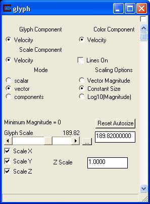
The control panel for glyph is shown in the figure above.
The Glyph component radio button list displays all data components passed to glyph. Glyph component determines which data component is used to scale and rotate the glyphs. The default selection is the first (0th) data component.
The Color Component radio button list also displays all data components passed to glyph. Color component determines which data component is used to color the glyphs. By default, the first (0th) data component is selected.
The Scale Component radio button list also displays all data components passed to glyph. Scale component determines which data component is used to scale the glyphs. By default, the first (0th) data component is selected.
The Mode radio buttons are used to determine how the glyph component is to be handled. The default is vector. The scalar mode scales the glyph by the magnitude of the scalar data value at each node. If the data is scalar, this mode should be used and the nodal data should be greater than or equal to zero, since negative scales factors for object size don't make a lot of sense and will create a distribution of sizes that is not physical. Use field math to adjust scalar data if necessary. The vector mode scales the glyph by the magnitude of the vector, and also rotates the glyph in 2 or 3 dimensions based on the vector subcomponent values. The component mode scales the glyph in 2 or 3 dimension using the magnitudes of the vector subcomponents. For example, a Cross3D glyph in a 3D vector field would have each of its three lines (X, Y, and Z) scaled by different vector subcomponents.
The Scaling Options radio buttons determine how the glyphs will be sized.
Vector Magnitude specifies the size of the glyphs will be proportional to the relative magnitude of the data component values at each node.
Constant size specifies the size of the glyphs will be determined directly by Glyph Scale.
Log10(Magnitude) specifies the size of the glyphs will be proportional to the log10 of the magnitude of the data component values at each node. This requires another parameter which is the Magnitude for Zero Length.
Magnitude for Zero Length is the vector magnitude at which the glyphs will be zero size. This establishes the minimum level for taking log values since the log of zero is undefined (minus infinity).
The Glyph Scale slider and type-in is used to control the size of the glyphs. The default is automatically computed based on your input data. If you change the auto-computed value, you can use the Reset Autosize button to recalculate a new size.
The Scale X, Scale Y, and Scale Z toggles determine how the glyph will be scaled. The default is to have all three on and scale the glyph in all three directions.
The Z Scale type in is z-exaggeration of the input data field.
Related Modules
-> gradient
© 1994-2018 ctech.com