![]()
General Module Function
The extrude module accepts any mesh and adds one to the dimensionality of the input by extruding the mesh in the Z direction. The interface enables changing the height scale for extruded cells and extruding by a constant, any nodal or cell data component. This module is often used with the Read_Shapefile module to convert polygonal shapefiles into extruded volumetric cells.
Module Input Ports
The extrude module has a single input port that accepts any non-volumetric mesh. Point, line, or polygonal input is accepted, as well as any number of mesh or cell data components.
Module Output Ports
The extrude module has two output ports. The blue/black output port is the new mesh which will have a dimensionality one greater than the input. The new mesh will include all of the nodal and cell data in the input field. The red port outputs a renderable object which will be colored by the first nodal data component in the input field, the first cell data component if the input field has no nodal data, or a constant color if the input mesh has no data components.
Module Control Panel

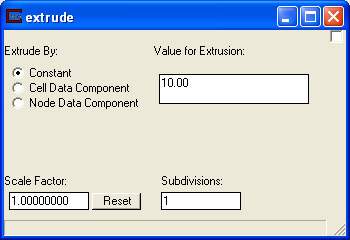
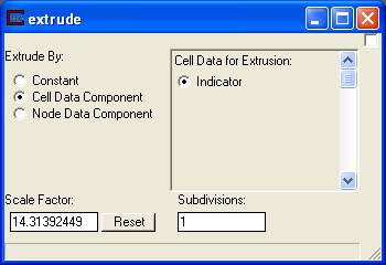
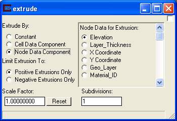
The control panel for extrude is shown above. The "Extrude By" radio buttons control the method of extrusion. The "Node/Cell Data for Extrusion" radio buttons determine which data component will be used. The output will contain all data components.
The Scale Factor is multiplied by the data value to determine the extrude height.
The Subdivisions field determines how many cells vertically to create.
When Constant is selected, the cells in the output mesh will be extruded by the "Value for Extrusion" times the "Scale Factor".

When Cell Data Component is chosen, the output cells will be extruded by the Scale Factor times the value of whichever cell data component is selected on the right.

When Node Data Component is chosen, the output cells will be extruded by the Scale Factor times the value of whichever nodal data component is selected on the right. With nodal data extrusion you must select "Positive Extrusions Only" or "Negative Extrusions Only". Since each node of a triangle or quadrilateral can have different values, it is possible for a single cell to have both positive and negative data values at its nodes. If this type of cell is extruded both directions, the cell topology can become tangled.
For this reason, nodal data extrusions must be limited to one direction. To extrude in both directions, merely use two extrude modules in parallel, one set to positive and the other to negative.
Related Modules
© 1994-2018 ctech.com