![]()
General Module Function
The orthoslice module is similar to the slice module, except limited to only displaying slice positions north-south (vertical), east-west (vertical) and horizontal. orthoslice subsets a structured field by extracting one slice plane and can only be orthogonal to the X, Y, or Z axis. Although less flexible in terms of capability, orthoslice is computationally more efficient.
Module Input Ports
orthoslice has one input port. Data passed to this port must contain a structured mesh (a field as opposed to a UCD) and Node_Data. The input can be 1D, 2D, or 3D.
Module Output Ports
orthoslice has two output ports. The leftmost output port creates a field with a new structured mesh of the same type as the input field. The mesh is the mesh of the slice. It contains the slice's Node_Data. The second output port sends a renderable version of the field (a slice) to the viewer.

Module Control Panel
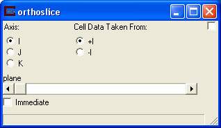
The control panel for orthoslice is shown in the figure above:
The axis selector chooses which axis (I, J, K) the orthoslice is perpendicular to. The default is I. If the field is 1D or 2D, three values are still displayed. Select the values meaningful for the input data.
The plane slider selects which plane to extract from the input. This is similar to the position slider in slice but, since the input is a field, the selection is based on the nodal dimensions of the axis of interest. Therefore, the range is 0 to the maximum nodal dimension of the axis. For example, for an orthoslice through a grid with dimension 20 x 20 x 10, the range in the x and y directions would be 0 to 20.
The Cell Data Taken From selector determines which side of the nodal suface the cell data should taken from. Since orthoslice "slices" between layers of cells, the data must be selected from one side or the other.
The Immediate toggle causes the display to update as you move the slider(s).
Related Modules
->slice
© 1994-2018 ctech.com