![]()
This is a deprecated module whose function has been superceded by constant_shell
General Module Function
The constant_shellmodule produces a surface of constant value within the data domain. Isosurfaces are essentially three-dimensional contour lines. Each instance of isosurface can produce only a singular isosurface. However, multiple instances may be used to create more than one isosurface in the same data set. The isosurface of one component may be colored by the value of another component (for example, the isosurface of concentration colored by uncertainty).
Module Input Ports
isosurface has two input ports. The leftmost port accepts unstructured mesh data. The second port provides a means to share the subsetting level of other modules.
Module Output Ports
isosurface has three output ports. The first output port (closest to the left) outputs a new unstructured mesh which contains tri (polytriangle mesh) cell types representing the isosurface. Nodal data sent to this output port consists of the interpolated values of the map component on the isosurface. The second port outputs a rendered geometry directly to the Viewer. The third output port provides a means to share the subsetting level of this module with others.

Module Control Panel
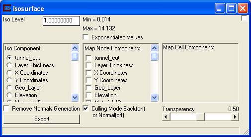
The control panel for isosurface is shown in the figure above.
The Iso Level type-in is used to set the level for subsetting the input field. If a value is chosen larger than the max value, the max value is placed in the edit box. Similarly, if a value less then the minimum is input, the minimum value is placed in the box. The default iso level value is the arithmetic average of the minimum and maximum values in the iso component. If your input data has been kriged with log processing, the values here will be the Log of your input data.
Selecting the Exponentiated Values will create a new field to appear that contains the exponentiated value of the Iso level.
Iso Components refers to the nodal data component used to create the subset of the original input field. When an iso component is selected, the min and max values of the variable are displayed next to the Iso Level type-in.
MapNodeComponents determines which nodal data components in an unstructured mesh will be sent to the leftmost output port. Also, the first map component selected will be used to color the output. If no component is selected the output will be colored by the first cell component mapped to the output. If no cell component is mapped the output will be a default white color.
The Map Cell Components option box selector lets you map cell data (if any) to the surfaces output by plume_volume. This is markedly faster than using interp_cell_data. The cell data will only be visible if all nodal data is unselected (under MapNodeComponents).
Related Modules
-> isolines
© 1994-2018 ctech.com