![]()
This is a deprecated module that has been supplanted byLoad_EVS_Field
General Module Function
The Read UCD module is used to read EVS Unstructured Cell Data (UCD) files. These files have a default .inp filename extension, and contain ASCII text. UCD files contain cell structure data and nodal or cell based data components. The format of a UCD file is discussed below. UCD files are created using Write_UCD , the MODFLOW_2_UCD module, or externally by the user. A typical use of Read UCD involves using Krig Geology and/or Krig_3D to krig a .apdv file, writing a UCD file of the Krig_3D output using Write UCD, and reading the UCD file into another network using Read UCD. This eliminates the need for re-kriging the data every time a data set is used. It is important to understand, however, that a UCD contains the range of property values that are output by a kriging module, which may or may not represent the entire actual range of the input data (the .apdv or .GEO file). The range of data output by kriging modules depends on the grid density and kriging parameters used to produce the data field. Uniform maximum and minimum values that are written to a UCD can be controlled in the kriging modules, or by using the set_minmax module.
Module Input Ports
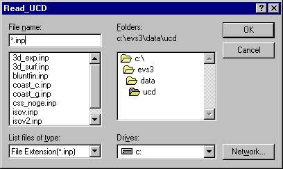
The Read UCD module is shown above. Read UCD has no input ports. It obtains the UCD input data by reading a file with a file browser.
Module Output Ports
Read UCD has one output port, which passes the mesh and data components to other modules. Data passed from Read UCD is usually sent to modules in the Subsetting and Processing Library.

Module Control Panel
The user interface for Read UCD consists solely of the file browser shown above. The file browser is used for selecting the UCD file (UCD files have a .inp extension). The default directory path is the \EVS\DATA\UCD. Double clicking on a filename or selecting a file name and choosing OK reads the selected UCD file into memory and closes the file browser. After a UCD file has been read into memory, the mesh and data components are passed to any downstream modules in the network. Selecting a different UCD file, after one has been read in, will replace the first UCD file's mesh and data components with the new UCD file's mesh and data components and all network modules will be updated with the new data.
The format of UCD files is very similar to that commonly employed by node based finite element models. Essentially, UCD files contain three different sections with a header line that describes the type and amount of data that is contained in each section. A UCD file cannot contain blank lines or lines with leading blanks. Comments can be present at the top of the file, but are not allowed in other parts of the file. Leading comment lines must begin with the "#" symbol. An example UCD file is presented below, with explanation lines describing the contents of the lines (which can not be present in actual UCD files) placed in brackets "{}" and colored magenta and italicized. If the user wishes to create or manipulate UCD files, they should examine some of the example UCD files contained in the EVS\DATA\UCD directory in a text editor to become familiar with the UCD structure. The file described below is the hex.inp example UCD file, which can be found in the sample UCD directory. This UCD file consists of one hexahedral cell with 8 nodes, and each node has a single scalar data value.
# Lines with leading "#" characters in a UCD file can be comments.
# The user can include any number of comment lines.
{The first section of data in the file begins with a header line, which describes the number of nodes in the model, the number of cells in the model, the number of nodal data components, the number of cell data components, and the number of model data components (cell and model data components are not currently used in EVS). The first section of the file looks like this:}
8 1 1 0 0 {8 nodes, 1 cell, 1 nodal data component, 0 cell data, 0 model data}
1 0.000 0.000 1.000 {node 1, xcoord = 0, ycoord = 0, zcoord = 1]
2 1.000 0.000 1.000 {node 2, xcoord = 1, ycoord = 0, zcoord = 1]
3 1.000 1.000 1.000 {node 3, xcoord = 1, ycoord = 1, zcoord = 1]
4 0.000 1.000 1.000 {and so forth for the 8 nodes in this hexahedron]
5 0.000 0.000 0.000
6 1.000 0.000 0.000
7 1.000 1.000 0.000
8 0.000 1.000 0.000
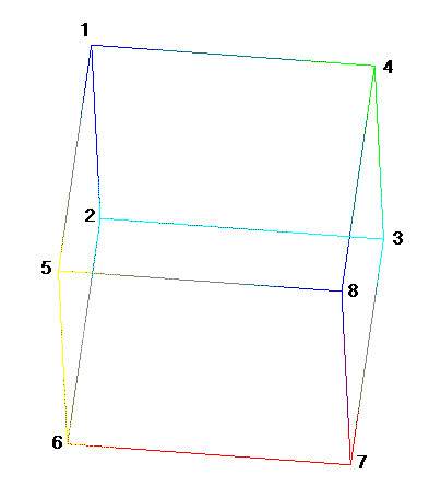
{The second section of the file contains the list of elements in the model, the material type (or layer) of each element, the type of element (EVS usually uses quads and hexahedrons), and the nodes that make up the vertices of the element, listed in order of connectivity starting from the upper left vertex, and progressing counterclockwise for each layer of vertices in the element (see the diagram below). Remember these lines starting with brackets are for explanation only and cannot actually be present in the file.}
1 1 hex 1 2 3 4 5 6 7 8 {Element 1, Material 1, Hexahedral Element Type,Node numbers for nodes at vertices of element. This element has 8 vertices, at nodes 1 through 8. Note that the nodes were identified by number in the first section of the file, and along with their X, Y, Z, coordinates}
{The third section of the file contains a first line that lists the number of data components for each node, and then a list of the number of properties belonging to each component. Most EVS modules output "scalar" properties, which by definition have only one property per data component. However, the MT3D model outputs a vector component describing the velocity of fluid flow at the model nodes, which has the three properties of X, Y, Z velocity present in one data component. An example of this type of "vector" data component is presented below.}
1 1 {One data component, One property in the first component "a scalar" The next n lines of the third section of the file contain text entries separated by commas, that describe the name and units of the property in each data component. There are as many of these text lines as there are data components.}
stress, lb/in**2 {Data Component 1 is the Stress property, Units are lb/in**2]
The last n lines in the third section of the file list the node numbers, and the values for the properties in each data component. There are as many lines as there are nodes in the model.}
1 4999.9999 {Node 1, 4999.9999 (Stress Property Value in lb/in**2)}
2 18749.9999 {Node 2, 18749.9999 (Stress Property Value in lb/in**2)}
3 37500.0000 { Node 3, and so on ...}
4 56250.0000
5 74999.9999
6 93750.0001
7 107500.0003
8 5000.0001
{The last node number and list of data component property values is the last line of the file.}
A more complex example of a UCD file is provided below, which is an edited version of the sample file sp0112.inp, which is located in the EVS\DATA\MODFLOW\PROB.SPI\SAMPLE directory. Note that this UCD file has no header lines, and has a vector property in the last nodal data component (in the third section of the file). Again, some explanations of the file structure are provided, which are enclosed in brackets "{}"and colored magenta. These are not in the actual UCD file.
22134 10500 12 0 0 {Line 1 of Section 1; 22134 nodes, 10500 elements, 12 nodal data components}
1 9625.112 10786.380 6.275 {Node 1, 9625.112 X Coord, 10786.380 Y Coord, 6.275 Z Coordinate}
2 9714.992 10742.550 6.367
3 9804.871 10698.710 6.581
4 9894.751 10654.870 6.939
5 9984.630 10611.030 7.581
. {Data lines for nodes 6 through 22130 Omitted from this example}
.
22131 12534.330 6029.657 -62.443
22132 12624.210 5985.820 -62.879
22133 12714.090 5941.983 -63.324
22134 12803.970 5898.146 -63.318 {Node 22134 is last in Model}
1 0 hex 1 52 53 2 1582 1633 1634 1583 {Line-1 of Section 2; Element 1, Material 0, Hex Elem., Nodes }
2 0 hex 2 53 54 3 1583 1634 1635 1584 {at vertices of element 1 are 1,52,53,2,1582,1633,1634,1583}
3 0 hex 3 54 55 4 1584 1635 1636 1585
4 0 hex 4 55 56 5 1585 1636 1637 1586
5 0 hex 5 56 57 6 1586 1637 1638 1587
. {Data lines for elements 6 through 10494 Omitted from this example}
.
10495 6 hex 20496 20547 20548 20497 22077 22128 22129 22078
10496 6 hex 20497 20548 20549 20498 22078 22129 22130 22079
10497 6 hex 20498 20549 20550 20499 22079 22130 22131 22080
10498 6 hex 20499 20550 20551 20500 22080 22131 22132 22081
10499 6 hex 20500 20551 20552 20501 22081 22132 22133 22082
10500 6 hex 20501 20552 20553 20502 22082 22133 22134 22083 {Element 10500,.Material 6...Last in Model}
10 1 1 1 1 1 1 1 1 1 3 {Line 1 of Section 3; 10 Data components, Comp.1 through 9 have 1 property, Comp 9 has 3}
head, feet {First data component is head in feet (a scalar property)}
drawdown, feet {Second data component is drawdown in feet}
thickness, feet {Third data component is layer thickness in feet}
Geolayer, number {Fourth data component is Geolayer number, which specifies which element material it beongs to}
Elevation, feet {And so forth...}
Conductivity, feet/day
Storage, unitless or 1/feet
Concentration, M/L^3
Change in Conc, M/L^3
Velocity, L/t {Velocity has three components, Vel in X, Vel in Y, Vel in Z, in L/t, a vector data component}
3 .895 .000 20.6 0 6.58 15.0 .250 .286E-03 -.143E-03 -.750E-02 .115E-01 .000
4 .900 .000 21.2 0 6.94 15.0 .250 .341E-03 -.314E-03 .000 .111E-01 .000
5 .900 .000 21.2 0 7.58 15.0 .250 .756E-05 -.171E-03 .000 .101E-01 .000
. {Data lines for nodes 6 through 22129 Omitted from this example}
.
22130 .735 .000 3.77 6 -63.0 105. .100E-05 .295E-02 -.667 -.525E-01 -.732E-01 .000
22131 .740 .000 3.85 6 -62.4 105. .100E-05 .504E-03 -.947 .000 -.330E-01 .000
22132 .740 .000 4.14 6 -62.9 105. .100E-05 .352E-06 -.733 .000 .501E-02 .000
22133 .740 .000 4.44 6 -63.3 105. .100E-05 .000 -.644 .000 .525E-01 .000
22134 .740 .000 4.45 6 -63.3 105. .100E-05 .000 -.643 .000 .525E-01 .000 {Node 22134, last in model}
The node numbering order for hexahedrons used by EVS is demonstrated in the following figure:
1 .890 .000 19.1 0 6.28 15.0 .250 .742E-07 .000 .000 .750E-02 .000 {Node 1, properties as listed above}
2 .890 .000 19.6 0 6.37 15.0 .250 .000 .000 .000 .590E-02 .000

The nodes are numbered starting in the upper left corner of a hexahedron or quadrilateral element, and increase first counterclockwise, and then downward and counterclockwise as shown.
Related Modules
© 1994-2018 ctech.com