![]()
General Module Function
The 3D Geology Map module creates 3-dimensional solid layers from the 2-dimensional surfaces produced by Krig_3D_Geology, to allow visualizations of the geologic layering of a system. It accomplishes this by creating a user specified distribution of nodes in the Z dimension between the top and bottom surfaces of each geologic layer.
The number of nodes specified for the Z Resolution may be distributed (proportionately) over the geologic layers in a manner that is approximately proportional to the fractional thickness of each layer relative to the total thickness of the geologic domain. In this case, at least three layers of nodes (2 layers of elements) will be placed in each geologic layer.
Module Input Ports
3D Geology map has only one input port, which typically receives its input from Krig_3D_Geology. However, it must be of the same type (blue-green-gray port), but may also come from Spline_Geology, or from multiple raster_to_geology modules passed through combine_geology.. Please note that if any portions of the input geology is NULL, these cells will be omitted from the grid that is created. This can save memory and provide a means to cut (in a Lego fashion) along boundaries.
Module Output Ports
3D Geology map has only one output port, which passes a three dimensional data field to modules downstream. In most typical networks, the output port is connected to Explode and Scale. Note that the scalar data components of layer thickness, x coordinate, y coordinate, Geo_Layer, Elevation, Material_ID and Depth are output from 3D Geology Map, which can be filtered by the select_data module for coloring of the output.

Module Control Panel
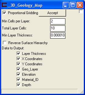
The control panel for 3D_Geology_Map is shown above.
Proportional Gridding - A toggle for activating the same algorithm for apportioning nodes in the Z direction as used in Krig_3D. The number of nodes specified for the Z Resolution will be distributed (proportionately) over the geologic layers in a manner that is approximately proportional to the fractional thickness of each layer relative to the total thickness of the geologic domain. In this case, at least three layers of nodes (2 layers of elements) will be placed in each geologic layer.
Min Cells per layer - A Type in for establishing a minimum number of cells (in the Z direction) per layer. The default is 2 cells which results in 3 nodes.
Total Layer Cells - A guide for establishing the total number of cells in the model. The reason the term guide is used is due to the possibility that the module could potentially produce more than the total. Here is an example of how this could occur:
If the Min Cells per layer times the number of layers is greater than the Total Layer Cells value, then the input will be superceded. (Example: The Total Layer Cells was 13, but there were 3 layers with Min Cells per Layer of 5, resulting in 15 cells).
NOTE: If Proportional Gridding is toggled off then only Min Cells per Layer is enabled. In this case, only the Min Cells per Layer input will be used for each layer of the model.
Data to Output – These toggles allow you to specify which data components to include in your output. Note that depth allows you to cut geologic layers at a constant distance below ground surface.
Reverse Surface Hierarchy – This toggle determines whether the surfaces will define layers in a normal (top to bottom) manner or reversed (if on). This topic is discussed in more detail in Workbook 12.
Minimum Layer Thickness forces layers thinner than the specified value to have a minimum thickness and therefore not pinch-out completely.
Further explanations of the use of 3D Geology Map are presented in Workbook2.
© 1994-2018 ctech.com