![]()
This is a deprecated module whose function has been superceded by thedraw_2D_linesmodule and thedraw_3D_linesmodule.
General Module Function
ClickSketch enables you to create a 2D drawing with individual clicks of the mouse. The mouse gesture for line creation is: depress the alt key and then click the right mouse button. The first click establishes the beginning point of the line segment and the second click establishes the end point. ClickSketch allows adding of points, erasing of region points, and closing a region. The lines, once drawn, will reside at an elevation of 0.0 with reference to the view plane of the current viewer. Therefore, it is recommended that drawing actions be made in a normalized view (from directly above the object) to ensure the line is drawn at a constant z-value. This module is commonly used to create 2D lines passed to the fence_cut module. Unlike most modules which create mesh data to used by other modules, the ClickSketch module receives input from the viewer, and also passes on field data to be used by other modules. NOTE: Currently in EVS the line will not display in the viewer window unless software renderer is chosen in the viewer instead of OpenGL.
Module Input Ports
ClickSketch has two input ports. This first input port is typically connected to one the viewer's pink output. The second input port is connected to the red output of the object within which the line will be drawn. Without an object, ClickSketch converts the drawing to a field in the camera's world space. With an object, ClickSketch converts the drawing to a field in the object's world space.
Module Output Ports
ClickSketch has two output ports. This first output port sends mesh and nodal data to downstream modules. The second output port sends the line as a renderable object to the viewer to be rendered.

Module Control Panel
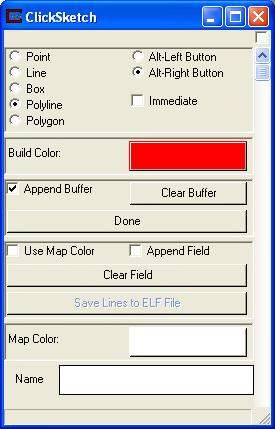
The ClickSketch user interface allows interactive creation of points or lines onto any connected object and then displays the points or lines in the viewer. One popular use for this functionality is for creation of line segments to create fence sections using the fence_cut module.
The first set of radio buttons allows picking which type of primitive to draw. Possible primitives are point, line. box, polyline, and polygon. The default is polyline because only polylines are supported with the fence_cut functionality (box and polygon uses polylines). To the right of those you can select the keyboard and mouse button sequence that is used to draw. For Version 4.5 the new default is Alt+Right Mouse Button.
The immediate toggle controls whether the output buffer is immediately written to (data passed to other modules) upon completion of a line segment. When the toggle is off, you must press the Done button to cause the output buffer to be written.
The build color sliders control the color of the drawn line. Remember the line will not display unless software renderer is selected in the viewer instead of OpenGL.
The append buffer toggle determines whether each time a line segment is completed it overwrites any previous primitive. If append buffer toggle is on, each time a primitive is built, it is appended to a previous line segment(s). By using append mode, you can build multiple primitives before mapping them to a field.
The Clear Buffer button causes the build buffer to be cleared of all points or line segments. The Done button causes all existing line segments to be passed to other modules as a field.
The map color sliders enable passing of color values to be passed as field data to other modules. These color values are only passed if the Use Map Color toggle is on. If the toggle is off, no color information is written to the field. If on, color information is written to the output field as cell data. This gives you the ability to specify color on a per primitive basis.
The Append Field toggle is on by default. By using append mode, you can incrementally build the field (for example fence sections). If the Append Field toggle is off, each time points or lines are mapped, any previous field is overwritten.
The Clear Field button erases any field previously created.
The map name box allows creating a name for the cell sets passed upon pressing the Done button.
The Save Lines to ELF File allows the user to save all of the created lines in the EVS Line File format (*.elf).
© 1994-2018 ctech.com