![]()
This is a deprecated module whose function has been superceded by contour_data
General Module Function
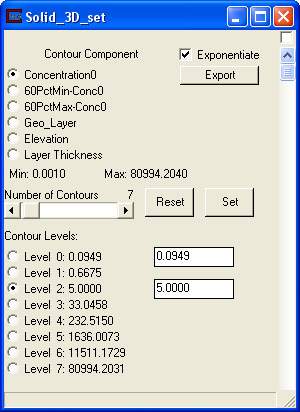
Solid_3D_Set is an enhancement to the Solid_3D module. The enhancement involves type-ins for setting non-linear threshold values for any number of threshold cutoffs. For example, 5 cutoffs between 0 and 100 would NOT have to be 0, 20,40, 60,etc, but instead could be 0.5, 5, 10, 25, and 50. The subsetting level is set by a user type-in value and the desired number of contour levels is set with a slider. The levels can be reset to initial values with the reset button, then the contours levels are adjusted and set by the user as needed.
Module Input Ports
Solid_3D_Set has two input ports.
The first (blue-black) port accepts unstructured mesh and nodal data.
The second port (blue-red-blue-beige) is found on only a few modules in EVS/MVS. The modules with this port are Solid_3D_set, solid_contour_set, isolines, Datamap_Editor, and Color_Legend.
These modules pass data corresponding to one or more subsetting levels (or solid contour levels). When this data is passed to Solid_3D_Set, it is used to set the precise break points where contours will occur. When this data is passed from Solid_3D_Set to other modules, the levels set in Solid_3D_Set will be reflected in those modules.
Module Output Ports
Solid_3D_Set has two output ports. The first output port (closest to the left) outputs a rendered geometry directly to the Viewer.
The second port (blue-red-blue-beige) is found on only a few modules in EVS/MVS. The modules with this port are Solid_3D_set, solid_contour_set, isolines, Datamap_Editor, and Color_Legend.
These modules pass data corresponding to one or more subsetting levels (or solid contour levels). When this data is passed to Solid_3D_Set, it is used to set the precise break points where contours will occur. When this data is passed from Solid_3D_Set to other modules, the levels set in Solid_3D_Set will be reflected in those modules.
![]()
The Export button causes additional output ports to appear as shown above.

Module Control Panel
The control panel for solid_3D_Set is shown in the figure above. The subsetting level of the selected component is changed by adjusting the Level Min type-in box. The user then adjusts the number of contours with the slider. By default, contour intervals are divided evenly between the Level Min and maximum value in the mesh. The process of setting user defined cutoffs requires the following order of steps:
first set the number of contours,
then set the Level Min
then set the contour level type-ins
then click the Set button.
If you wish to specify a different number of contours, all levels will be re-set to even increment contour spacing and the above process must be repeated. If you have set the contour levels but then want to shave away using level min, you simply type-in the new Level Min and click set. Solid_3D_Set will automatically shift all levels which are currently below this new Level Min to match it. The result is that all contour levels remain constant while shaving away to a higher concentration.
The Export button adds additional output ports to the module to facilitate passing text and numeric data to other modules. The result is shown above. The additional ports represent:
Iso_Component name: This is a string with the name ot the selected data component.
Above/Below: This is a string containing the word "Above" or "Below" depending on the state of the toggle above.
Iso_Level: This is a real number representing the subsetting level.
Exponentiated Iso_Level: This is a real number representing the exponentiated subsetting level.
Related Modules
-> isolines
-> Solid_3D
© 1994-2018 ctech.com